Community
- Forums Home
- >
- Community Archive - Read Only
- >
- Simulation Mechanical Community
- >
- Simulation Mechanical Forum
- >
- Re: excentric centroid (no match) beam element
Simulation Mechanical Forums (Read-Only)
Welcome to Autodesk’s Simulation Mechanical Forums. Share your knowledge, ask questions, and explore popular Simulation Mechanical topics.
Turn on suggestions
Auto-suggest helps you quickly narrow down your search results by suggesting possible matches as you type.
excentric centroid (no match) beam element
9 REPLIES 9
Reply
Topic Options
- Subscribe to RSS Feed
- Mark Topic as New
- Mark Topic as Read
- Float this Topic for Current User
- Bookmark
- Subscribe
- Printer Friendly Page
Message 1 of 10
Anonymous
1040 Views, 9 Replies
09-10-2012
03:21 PM
- Mark as New
- Bookmark
- Subscribe
- Mute
- Subscribe to RSS Feed
- Permalink
- Report
09-10-2012
03:21 PM
excentric centroid (no match) beam element
Coul you please help me
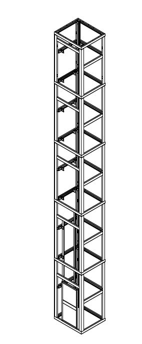
I have a shaft for elevator
I want to do an analysis FEM with beam elements.
The difficulty I have is that the centroids are not match
add pictures
Than you
9 REPLIES 9
Message 2 of 10
09-11-2012
09:45 AM
- Mark as New
- Bookmark
- Subscribe
- Mute
- Subscribe to RSS Feed
- Permalink
- Report
09-11-2012
09:45 AM
One way to do it would be like this:
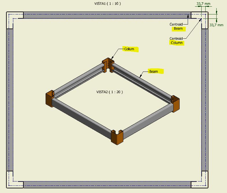
- draw the beams at their centroid, but make them 33,7 mm shorter on each end.
- draw the columns at their centroid.
- use a different part number to draw connecting lines, 33.7 mm long, between the end of the beams and the column. You would give these elements a large stiffness (~100 to 1000 times stronger) and massless.
After you analyze your beam model (or even before!), you may want to create a plate model of one of the joints, and (manually) apply the forces from the beam model to the ends of the sections in the plate model. (See attached image.) My concern is that the "flanges" of the columns will flex the open cross-section and allow some relatively independent rotation of the beams. The beam element model will not include this type of effect.
Message 3 of 10
09-13-2012
08:44 AM
- Mark as New
- Bookmark
- Subscribe
- Mute
- Subscribe to RSS Feed
- Permalink
- Report
09-13-2012
08:44 AM
Can you explain how to go about extracting the forces and moments for a cross-section after running a simulation?
Message 4 of 10
09-15-2012
08:02 AM
- Mark as New
- Bookmark
- Subscribe
- Mute
- Subscribe to RSS Feed
- Permalink
- Report
09-15-2012
08:02 AM
"Results Contours > Other Results > Element Forces" and then get the 6 results at each point from the commands on the "Results Inquire" tab.
Message 5 of 10
Anonymous
in reply to:
Anonymous
09-17-2012
11:44 AM
- Mark as New
- Bookmark
- Subscribe
- Mute
- Subscribe to RSS Feed
- Permalink
- Report
09-17-2012
11:44 AM
Thanks John
I have an additional questions
I have analysed the model with beam elements. I have used beam elements, beam elements with large stiffness and end release.
I have extracted the forces and moments of the baeam analysis
I have analysed one of the critical joints with this forces aplly on the end of the plate analysis.
How can apply boundary condictions on the joint analisys (plate elements)? the model is free to move
Axial force result on the node with (-) sign is compression forces?
add pictures and file
thanks
Message 7 of 10
09-17-2012
12:23 PM
- Mark as New
- Bookmark
- Subscribe
- Mute
- Subscribe to RSS Feed
- Permalink
- Report
09-17-2012
12:23 PM
Hi jjohnson,
The forces and moments on the sub-model should be in balance, theoretically. That is, sum of foces in X = 0, sum of foces in Y = 0, up through sum of moments about Z = 0. Therefore, you can apply some constraints almost anywhere to take up any imbalance in the applied loads.
- The best place would be in the area where the stresses are the lowest.
- I suggest adding three (3) "Setup > Constraints > 3D Spring Supports" to arbitrary nodes as long as they are not all in a straight line. (see attached image) Fix the springs in all three directions (X, Y, Z) and enter a small stiffness. (A small stiffness may be the amount of load in one direction divided by the displacement in that direction, divided by 100.)
- After running the analysis, look at the forces in the 3D springs ("Results Contours > Other Results > Element Forces > Axial Force") to confirm that the amount of load in them is small and insignificant.
Regarding the directions of the load, you will need to read the section "Element Forces and Moments" on this page in the Help documentation: Linear Results Menu.
Message 8 of 10
12-11-2012
06:06 AM
- Mark as New
- Bookmark
- Subscribe
- Mute
- Subscribe to RSS Feed
- Permalink
- Report
12-11-2012
06:06 AM
Good morning John
I have obtained excellent results with beam model. them are logical results.
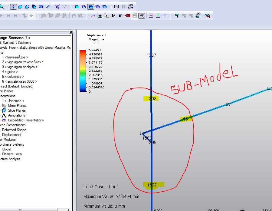
I have problem with sub-model
I have used the nodes 1398, 1597 anf 56 for transfer forces to the sub-model
The forces and moments on the sub-model are in balance
I have used nodal rigid boundaries on the sub-model fixed in X, Y and Z with 20 N/mm for the stifness
John, why the deformations are so high? I have any error in the submodel?
add files model and sub-model
Thanks
Message 9 of 10
12-11-2012
10:08 AM
- Mark as New
- Bookmark
- Subscribe
- Mute
- Subscribe to RSS Feed
- Permalink
- Report
12-11-2012
10:08 AM
Hmm. That's a good question. I will need to study it to see if I see anything wrong.
In the mean time, is the plate model displacing in the same direction as the beam model? I suspect that interpretting the direction of the force and moment results from the beam model is not straight forward, so applying them to the plate model with the proper sign or direction could be tricky. If the plate model is not deflecting like the beam model, that could help diagnose the problem.
Message 10 of 10
12-11-2012
11:37 AM
- Mark as New
- Bookmark
- Subscribe
- Mute
- Subscribe to RSS Feed
- Permalink
- Report
12-11-2012
11:37 AM
Thank you John
I have the following interpretation about the local sign convection for the beam elements
Add picture and original model
Reply
Topic Options
- Subscribe to RSS Feed
- Mark Topic as New
- Mark Topic as Read
- Float this Topic for Current User
- Bookmark
- Subscribe
- Printer Friendly Page
