Community
- Forums Home
- >
- Community Archive - Read Only
- >
- Simulation Mechanical Community
- >
- Simulation Mechanical Forum
- >
- Re: Contact between two surface parts.
Simulation Mechanical Forums (Read-Only)
Welcome to Autodesk’s Simulation Mechanical Forums. Share your knowledge, ask questions, and explore popular Simulation Mechanical topics.
Turn on suggestions
Auto-suggest helps you quickly narrow down your search results by suggesting possible matches as you type.
Contact between two surface parts.
6 REPLIES 6
SOLVED
Reply
Topic Options
- Subscribe to RSS Feed
- Mark Topic as New
- Mark Topic as Read
- Float this Topic for Current User
- Bookmark
- Subscribe
- Printer Friendly Page
Message 1 of 7
12-06-2013
09:07 AM
- Mark as New
- Bookmark
- Subscribe
- Mute
- Subscribe to RSS Feed
- Permalink
- Report
12-06-2013
09:07 AM
Hi,
I have two mid plane surface which i want to connect together. The plate/shell type of mesh is applied to all surfaces (Becasue of surface model).
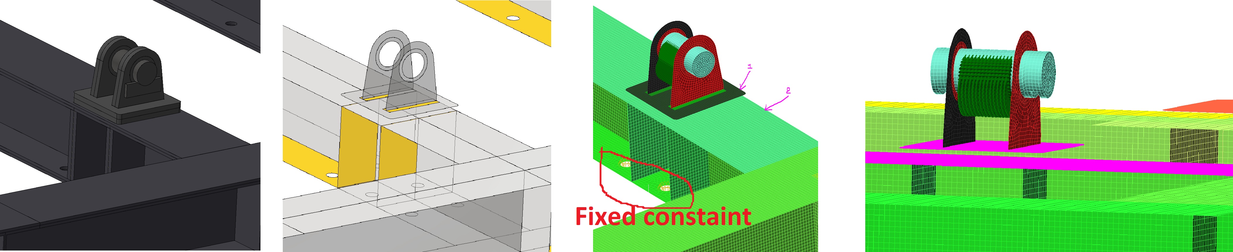
could you please explain me how cant i connect two surface together (there is gape between two surface becasue of they are mid plane surfaces of two solid parts_Please check atteched picture) the bottom one is fixed and the force is applied on the bolt.
Solved! Go to Solution.
Solved by AstroJohnPE. Go to Solution.
Solved by AstroJohnPE. Go to Solution.
6 REPLIES 6
Message 2 of 7
12-07-2013
07:16 AM
- Mark as New
- Bookmark
- Subscribe
- Mute
- Subscribe to RSS Feed
- Permalink
- Report
12-07-2013
07:16 AM
Hi Vikas,
If you are performing a linear analyis, then try the "Draw > Design > Contact Elements" command. This will draw line elements (on a new part) between the two surfaces. Use the option to limit the length of the elements to a length slightly greater than the distance between the two surfaces.
Then, how you define the elements depends on how you want to consider the two parts to be connected. If you want to consider them rigidly connected together, then make the element type Beam and give them relatively stiff properties. If the two parts are bolted together and you want to consider the potential separation of the two surfaces, define the element type as Gap, but make a few of them (4?) beam elements to represent the bolts and to keep everything together.
Reply
Message 3 of 7
12-10-2013
01:04 AM
- Mark as New
- Bookmark
- Subscribe
- Mute
- Subscribe to RSS Feed
- Permalink
- Report
12-10-2013
01:04 AM
Hei
John
Thank you very much for your reply,
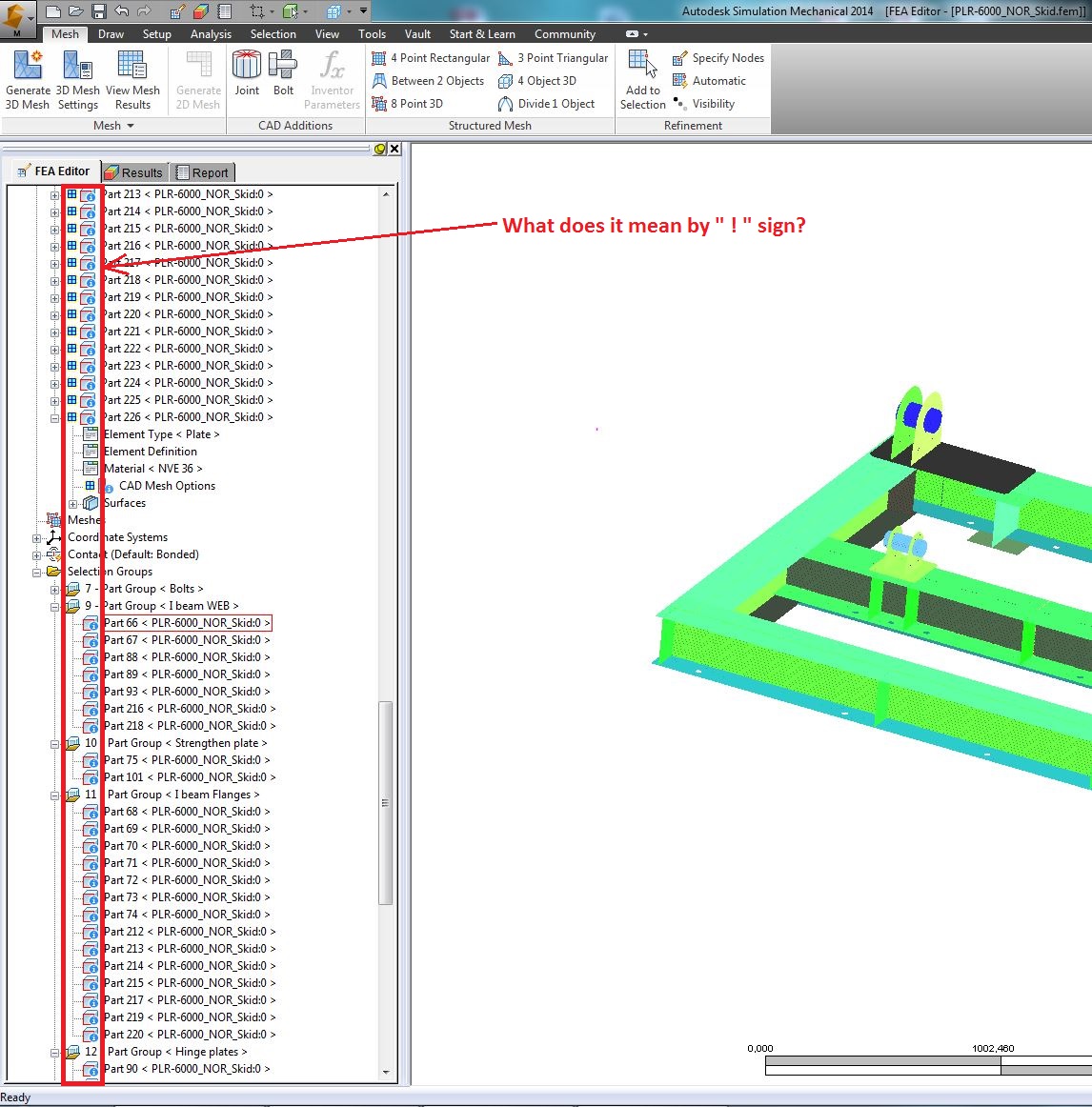
In the same surface model i have some doubt. Could you please tell me what does it mean by " ! " sign in CAD mesh options.
For information, i am performing static linear analysis. and the model type is surface model.
could also please tell me what kind of contact or element should i put between two plates as shown in 2nd figure? is it ok if i put the contact elements in bwtween (as you replied first time) ?
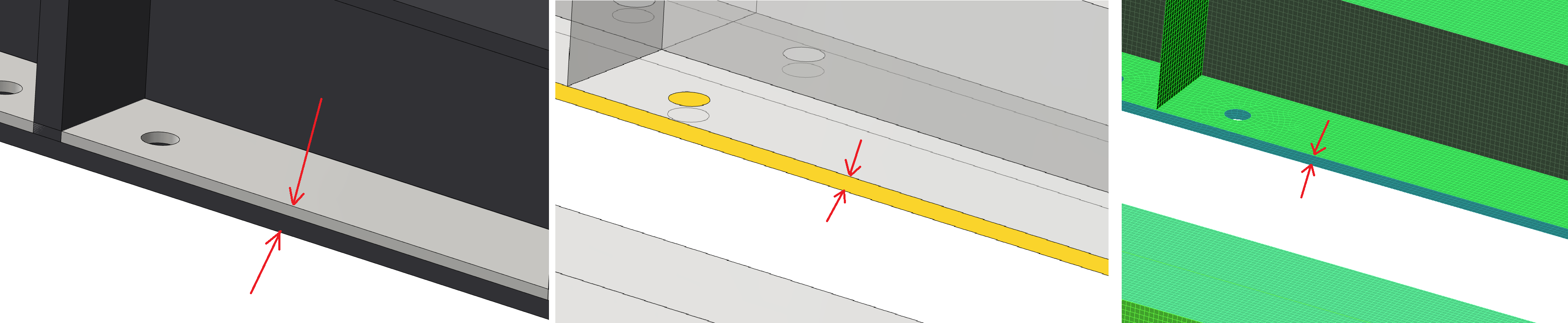
Those two solid plates are weled together from edges all around. as you can see in 2nd figure i have put midplane surfaces so now i have gape between those two surfaces.
Thank you in advance
Vikas
Message 4 of 7
12-10-2013
10:44 AM
- Mark as New
- Bookmark
- Subscribe
- Mute
- Subscribe to RSS Feed
- Permalink
- Report
12-10-2013
10:44 AM
Hi Vikas, here are some options.
- Since the two plates are in contact and welded around the edges, I would assume that they behave like 1 plate with the combined thickness. If you agree, you can eliminate the bottom plate and make the upper plate twice as thick (or whatever the sum of the two thicknesses are).
- The fact that the two plates are only connected around the edges may be important in some cases. What you would need to do in this case is draw lines between the two plates (as explained before) on two different part numbers. The lines around the edges would become beam elements in order to transfer the forces and moments between the plates. The remaining lines would be gap elements to detect where the two plates come into contact and where they separate. Note that adding contact or gap elements to the model will increase the runtime because the solution becomes iterative. It could be 3 times longer, 200 times longer, or even longer (unusual situation, I think).
About the "!" on the parts, it is indicating that the software thinks something is wrong. If I remember correctly, you can right-click on the line and choose one of the commands (mesh results?) to see what the message is.
But remember: the software does not know what you are doing. It just has a set of rules that it must follow. It does not really know if a warning will cause any problems. For that matter, it does not know that a model with no warnings or errors is a good model. What counts is what the model looks like in the Results environment (any missing elements, either on the surface or inside a volume?), what the applied loads look like (are the pressure arrows in the proper direction, etc), and what the results indicate (do parts come apart or pass through each other? Do the reactions equal the expected load?, etc).
Reply
Message 5 of 7
12-11-2013
12:21 AM
- Mark as New
- Bookmark
- Subscribe
- Mute
- Subscribe to RSS Feed
- Permalink
- Report
12-11-2013
12:21 AM
Hei
John,
THANK YOU VERY MUCH for you very well explained reply .
I will try as you replied and get back to you if i will have any more question.
Thank you again
Vikas
Message 6 of 7
12-19-2013
08:51 AM
- Mark as New
- Bookmark
- Subscribe
- Mute
- Subscribe to RSS Feed
- Permalink
- Report
12-19-2013
08:51 AM
Hei
I have one more question about gravity,
I want to apply gravity in 3 direction , I meant my gravity should work at 20 degree in X-Y plane (20 degree angel with -Y axis in counter clockwise direction) and 10 degree Y-Z plane (10 degree angel with -Y axis in clockwise direction)
and for that I have applied multipliers as (I want to set standard gravity 9810 mm/s2),
X= 0.34202
Y= 0.92541
Z= 0.16317
But once I put given multiplier in gravity dialog box, and click OK, the gravity symbol (Apple) becomes inactive.
Could you please explain me why?
(if I put anyone multiplier as 1, regardless rest of two multipliers it shows gravity active. Can you please tell me why?
Vikas
Message 7 of 7
12-20-2013
05:39 AM
- Mark as New
- Bookmark
- Subscribe
- Mute
- Subscribe to RSS Feed
- Permalink
- Report
12-20-2013
05:39 AM
It sounds like a bug to me. I suggest that you submit it to technical support so that they can write a bug report.
I think it is highly unlikely that it affects the analysis at all, but you should do a simple test to make sure. This test would also be important for tech support to evaluate the importance of the bug.
Reply
Topic Options
- Subscribe to RSS Feed
- Mark Topic as New
- Mark Topic as Read
- Float this Topic for Current User
- Bookmark
- Subscribe
- Printer Friendly Page
Forums Links
Can't find what you're looking for? Ask the community or share your knowledge.
Post to forums
