Community
- Forums Home
- >
- Community Archive - Read Only
- >
- Simulation Mechanical Community
- >
- Simulation Mechanical Forum
- >
- Re: Connecting plates to solids
Simulation Mechanical Forums (Read-Only)
Welcome to Autodesk’s Simulation Mechanical Forums. Share your knowledge, ask questions, and explore popular Simulation Mechanical topics.
Turn on suggestions
Auto-suggest helps you quickly narrow down your search results by suggesting possible matches as you type.
Reply
Topic Options
- Subscribe to RSS Feed
- Mark Topic as New
- Mark Topic as Read
- Float this Topic for Current User
- Bookmark
- Subscribe
- Printer Friendly Page
Message 1 of 7
Anonymous
1262 Views, 6 Replies
08-21-2012
01:24 PM
- Mark as New
- Bookmark
- Subscribe
- Mute
- Subscribe to RSS Feed
- Permalink
- Report
08-21-2012
01:24 PM
How can I obtain the connection between this plate and solid parts.
add pictures
Thank you
Solved! Go to Solution.
Solved by AstroJohnPE. Go to Solution.
6 REPLIES 6
Message 2 of 7
08-21-2012
02:44 PM
- Mark as New
- Bookmark
- Subscribe
- Mute
- Subscribe to RSS Feed
- Permalink
- Report
08-21-2012
02:44 PM
Hi JJ,
Your model is incorrect to be used as plate elements. What you actually have is "sheet metal" folded around a a channel, and then the channel was slipped out. So the brick element with the load is bonded to the "outside face" of the channel. By exaggerating the displacement, it looks as if the outside face of the bottom flange of the channel is passing through the inside face of the bottom flange of the channel.
Make sense? See my attached images and "Help > Simulation Mechanical > Mesh Models > Mesh Overview > Meshing CAD Solid Models > Model Mesh Settings".
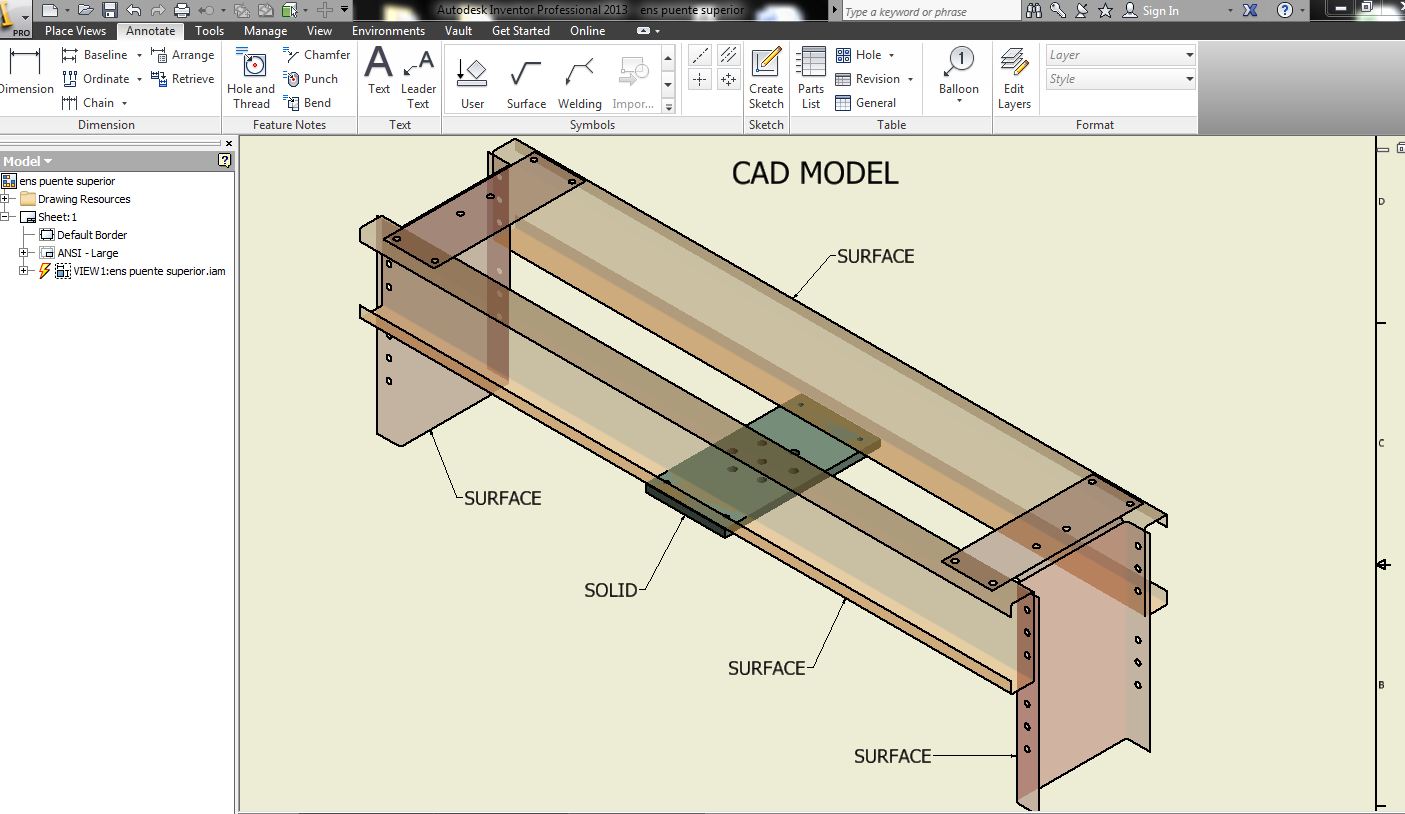
You should create a model using solids and surfaces in Inventor where the surface parts are in contact with the solid parts, and the surface parts will become the plate elements in Sim Mechanical.
John Holtz, P.E.
Global Product Support
Autodesk, Inc.
If not provided already, be sure to indicate the version of Inventor Nastran you are using!
"The knowledge you seek is at knowledge.autodesk.com" - Confucius 😉
Message 3 of 7
Anonymous
in reply to:
Anonymous
08-23-2012
07:47 AM
- Mark as New
- Bookmark
- Subscribe
- Mute
- Subscribe to RSS Feed
- Permalink
- Report
08-23-2012
07:47 AM
Thanks John
I have created a new model using surfaces in inventor where the surfaces parts are in contact with the solid part.
When I open the new model in Sim mechanical, I can not to see the surface parts, only I can to see the solid part.
Is not possible import to Sim Mechanical mixed parts (surfaces and solids) from inventor?
Add picture
Thanks
Message 4 of 7
08-23-2012
09:02 AM
- Mark as New
- Bookmark
- Subscribe
- Mute
- Subscribe to RSS Feed
- Permalink
- Report
08-23-2012
09:02 AM
Sorry, I did not pick up on the fact that you are using older software. (I think 2011 from the last image you attached.) The capability to import solids and surfaces in the same assembly was added to version 2013 (the current version).
I do not know if the step format supports solids and surfaces, but it is worth a try. Otherwise, you could
- In Simulation, save the current solid model to a new name.
- In Inventor, suppress the brick parts, leaving only the surface parts.
- Push the surface model to Simulation.
- In Simulation, use the "File > Merge" command and merge in the solid model. Because both models were created from the same assembly, everything should match up.
- Set the Model Mesh Settings to "Plate/Shell".
- Right-click on the solid parts and set the Part Mesh Settings to Solid.
- Mesh the model.
John Holtz, P.E.
Global Product Support
Autodesk, Inc.
If not provided already, be sure to indicate the version of Inventor Nastran you are using!
"The knowledge you seek is at knowledge.autodesk.com" - Confucius 😉
Message 5 of 7
08-26-2012
07:25 PM
- Mark as New
- Bookmark
- Subscribe
- Mute
- Subscribe to RSS Feed
- Permalink
- Report
08-26-2012
07:25 PM
Thanks John I have created a new model using surfaces in inventor where the surfaces parts are in contact with the solid part. When I open the new model in Sim mechanical, I can not to see the surface parts, only I can to see the solid part. Is not possible import to Sim Mechanical mixed parts (surfaces and solids) from inventor? Add picture Thanks ----------- La informaci?n adjunta es exclusiva para la persona a la cual se dirige este mensaje, la cual puede contener informaci?n confidencial y/o material privilegiado. Cualquier revisi?n, retransmisi?n, diseminaci?n o uso del mismo, as? como cualquier acci?n que se tome respecto a la informaci?n contenida, por personas o entidades diferentes al prop?sito original de la misma, es ilegal. Si usted recibe este mensaje por error, favor notif?queme y elimine este material. Gracias. ? ? ?
Message 6 of 7
Anonymous
in reply to:
Anonymous
08-30-2012
07:25 AM
- Mark as New
- Bookmark
- Subscribe
- Mute
- Subscribe to RSS Feed
- Permalink
- Report
08-30-2012
07:25 AM
Thanks John
Unfortunately Assembly models using shells/plate to not import into algor 2011 properly. In this moment We are not have Autodesk mechanical 2013.
By the above I can not to do this:
In Simulation, save the current solid model to a new name. In Inventor, suppress the brick parts, leaving only the surface parts. Push the surface model to Simulation. In Simulation, use the "File > Merge" command and merge in the solid model. Because both models were created from the same assembly, everything should match up. Set the Model Mesh Settings to "Plate/Shell". Right-click on the solid parts and set the Part Mesh Settings to Solid. Mesh the model.
I have done the following:
- I have created a new model in inventor (iam) using surfaces and solid.
- I have created a derive assembly model in inventor (ipt) using the option “maintain each solid as solid body”
- In simulation Set the Model Mesh Settings to "Plate/Shell". Right-click on the solid parts and set the Part Mesh Settings to Solid
- Mesh the model.
Results: (add pictures in zip file)
Displacements 0,85 mm
Stress 209 MPa
I have made calculations by hand and the displacements are very similar 0,79 mm. The stress is very different 70 MPa (model may have singularities)
I have a questions:
Is correct to make derive assembly in Inventor (surfaces and solid) and open them in simulation? I prefer to work with inventor instead of step files.
Can I interpret the height stress to be a singularities?
Thank you
Message 7 of 7
08-30-2012
12:35 PM
- Mark as New
- Bookmark
- Subscribe
- Mute
- Subscribe to RSS Feed
- Permalink
- Report
08-30-2012
12:35 PM
Hi,
Based on what I can see from the images, it looks like the model is correct. And I agree that the highest stress is most likely a singularity. You can check by adding a refinement point at those spots to create a really fine mesh. If the stress goes way up, it is a singularity.
What do other engineers do in this type of situation? Look at the stresses in the nodes around the singularity and average those? Or even if the stress is accurate, it indicates that there will be some very local yielding and don't worry about that?
Reply
Topic Options
- Subscribe to RSS Feed
- Mark Topic as New
- Mark Topic as Read
- Float this Topic for Current User
- Bookmark
- Subscribe
- Printer Friendly Page
Forums Links
Can't find what you're looking for? Ask the community or share your knowledge.
Post to forums
