Community
- Forums Home
- >
- CFD Community
- >
- CFD Forum
- >
- Re: Problems with extracting aerodynamic data for a flight simulator
CFD Forum
Welcome to Autodesk’s CFD Forums. Share your knowledge, ask questions, and explore popular CFD topics.
Turn on suggestions
Auto-suggest helps you quickly narrow down your search results by suggesting possible matches as you type.
Reply
Topic Options
- Subscribe to RSS Feed
- Mark Topic as New
- Mark Topic as Read
- Float this Topic for Current User
- Bookmark
- Subscribe
- Printer Friendly Page
Message 1 of 16
Anonymous
1191 Views, 15 Replies
07-22-2014
04:10 AM
- Mark as New
- Bookmark
- Subscribe
- Mute
- Subscribe to RSS Feed
- Permalink
- Report
07-22-2014
04:10 AM
Problems with extracting aerodynamic data for a flight simulator
So I am trying to extract aerodynamic data (Cm,Cn,Cl,CL,CN,CD) out of a CAD-model in both different aerodynamic angles and in different Mach's. Is there any tutorial or something out there that I have missed? I've been through the official ones (drag coefficient for the car and supersonic simulation for the bullet) but doing these generates data that doesnt match the data I already have from real wind-tunnel tests. Sometimes it matches somewhat but not always. I am currently wondering about the Torque-axis in the wall-calculator, is this to be set to 0 or use the suggested values to have it measure in the middle of the model? Whats odd is that changing the velocity gives different standardized coefficient. The formula I use is: Coefficient=Total Moment/(Dynamic Pressure * Real aircraft area * Total area as shown in Wall Calculator)
Any suggestions?
15 REPLIES 15
Message 2 of 16
Anonymous
in reply to:
Anonymous
07-25-2014
12:45 AM
- Mark as New
- Bookmark
- Subscribe
- Mute
- Subscribe to RSS Feed
- Permalink
- Report
07-25-2014
12:45 AM
Hi RagnarDa !
I faced the same problem as Autodesk Simulation CFD doesn't provide direct aerodynamics data like Cd or Cl like ANSYS Fluent. You have to calculate those from Drag force and Lift Force using wall calculator of Simulation CFD.
I found this pdf that i attached helpful.
Hope it would help. Thanks!
Message 4 of 16
07-25-2014
06:41 AM
- Mark as New
- Bookmark
- Subscribe
- Mute
- Subscribe to RSS Feed
- Permalink
- Report
07-25-2014
06:41 AM
The front area number is usually the chord length (in the flow direction) of the body or air-foil.
Hope this helps.

Message 7 of 16
07-31-2014
03:58 AM
- Mark as New
- Bookmark
- Subscribe
- Mute
- Subscribe to RSS Feed
- Permalink
- Report
07-31-2014
03:58 AM
Hi OmkarJ!
thanks! 🙂 actually this sketch is not mine,took it from a video used in sustainabilityworkshop by autodesk!
Message 8 of 16
Anonymous
in reply to:
Anonymous
08-19-2014
01:07 AM
- Mark as New
- Bookmark
- Subscribe
- Mute
- Subscribe to RSS Feed
- Permalink
- Report
08-19-2014
01:07 AM
Thanks for all the replys! The replies didn't help me though. When using the solutions that is suggested I get completely erronious results. An example:
If I test my model at 30 alpha 0 beta ~around Mach 0.5 (171.605 m/s) at sea level conditions i get the following results in the wall calculator (I removed the six walls of the bounding box from the calculations):
Summary -------------------
Total area 224.348 m^2
TOTAL FX -101726 Newton
TOTAL FY 2769050 Newton
TOTAL FZ -9520.9 Newton
Center of Force about X-Axis (Y-Z) 5.52947 6.87737 m
Center of Force about Y-Axis (X-Z) 1.19719 6.8917 m
Center of Force about Z-Axis (X-Y) 0.121217 5.70515 m
TOTAL MX -19096400 N-m
TOTAL MY -689668 N-m
TOTAL MZ 916020 N-m
Torque 916020 N-m
I am unsure which one of the moments is the pitch but if I calculate using MX (???) which is largest I get:
q = 0.5 * 1.2041 * (171.605 * 171.605) = 17729.3345808512
Cm = -19096400 / (q * 43 * 7.4) = -3.3850017048
which is far from my reference which is a wind tunnel testing data and is around -0.075. The 43 is the wing area and 7.4 is the chord length.
What is also odd is that if I change the velocity I get yet other values.
Any help?
Message 9 of 16
Anonymous
in reply to:
Anonymous
08-19-2014
06:02 AM
- Mark as New
- Bookmark
- Subscribe
- Mute
- Subscribe to RSS Feed
- Permalink
- Report
08-19-2014
06:02 AM
Note that you must be using the same moment reference axis to match published data. Most airoil data where a pitching moment is given has the reference at quarter chord; some use the leading edge (see notes here, for example: http://www.dept.aoe.vt.edu/~lutze/AOE3104/airfoilwings.pdf).
In SimCFD you do this in the wall calculator by selecting "Torque" and assigning a point on the centerline at the quarter chord location, and assign the axis to point in the direction of the pitch axis.
Message 10 of 16
Anonymous
in reply to:
Anonymous
08-19-2014
06:03 AM
- Mark as New
- Bookmark
- Subscribe
- Mute
- Subscribe to RSS Feed
- Permalink
- Report
08-19-2014
06:03 AM
Also, try at a much lower angle of attack, say 2 to 5 degrees -- most airfoils will stall above 12-15 degrees pitch so the data will be poor.
Message 11 of 16
Anonymous
in reply to:
Anonymous
08-19-2014
06:35 AM
- Mark as New
- Bookmark
- Subscribe
- Mute
- Subscribe to RSS Feed
- Permalink
- Report
08-19-2014
06:35 AM
Thanks for trying to help me, but first of all my model isn't a individual airfoil but a whole airframe. Secondly, my reference wind tunnel data describes the formulas and all the different measurements (reference chord, wing area and wing span) that are used to standardise the coefficients. My model is scaled to the real version. I did try lower angles, but only went so far as 10 alpha or 10 beta and they are still off by orders of magnitude. Changing the axis position doesn't do anything and changing the torque direction only changes the output of the torque line and is the same as the others, or maybe I don't understand something. My reference contains data for up to 60 degrees and my aim is to complete it with wind data for angles all around the design.
Message 12 of 16
08-20-2014
06:13 AM
- Mark as New
- Bookmark
- Subscribe
- Mute
- Subscribe to RSS Feed
- Permalink
- Report
08-20-2014
06:13 AM
How did the results look for 0 alpha 0 beta? Why not start there first?
Best regards,
Royce.Abel
Technical Support Manager
Message 13 of 16
Anonymous
in reply to:
Anonymous
08-21-2014
01:01 AM
- Mark as New
- Bookmark
- Subscribe
- Mute
- Subscribe to RSS Feed
- Permalink
- Report
08-21-2014
01:01 AM
It looks like this at M0.3:
Total area 224.353
TOTAL FX -21508.7
TOTAL FY 17295.7
TOTAL FZ 13924.8
Center of Force about X-Axis (Y-Z) 5.53313
Center of Force about Y-Axis (X-Z) 0.146436
Center of Force about Z-Axis (X-Y) -1.53812
TOTAL MX -56248.5
TOTAL MY -149756
TOTAL MZ 96001.1
Torque -86640.4
Velocity: 102.963
Density: 1.20473
Dynamic pressure 6385.8998836077
Which gives
C_m -0.0258761279 (should be around -0.01)
C_n? -0.0509805239 (should be 0)
C_l? 0.0326810704 (should be 0)
I guess these could be attributed to errors in my CFD-model but usually the difference is orders of magnitude wrong.
Message 14 of 16
Anonymous
in reply to:
Anonymous
08-21-2014
12:39 PM
- Mark as New
- Bookmark
- Subscribe
- Mute
- Subscribe to RSS Feed
- Permalink
- Report
08-21-2014
12:39 PM
Glad to hear it's coming within an order of magintude... but it's really hard to diagnose without more detail. Can you upload a picture, preferably one that illustrates your meshing, and showing the torque axis you're using?
I would highly recommend doing a very simple model with only a few surfaces and a well documented result, and getting the coefficients to match for that setup first. Start at a low angle of attack and low mach, and try to match CL within 10% and CD within 30%, and CM should follow if the reference axes match. Then see if pitch changes (alpha) produce the expected results first, and then yaw changes (beta). Only then go to higher mach (again starting at low alpha and no beta) and make sure compressibility is enabled and variable air material used if needed. Then increase alpha, etc.
Message 15 of 16
Anonymous
in reply to:
Anonymous
08-23-2014
03:25 AM
- Mark as New
- Bookmark
- Subscribe
- Mute
- Subscribe to RSS Feed
- Permalink
- Report
08-23-2014
03:25 AM
Here's my model. I know it isn't super-accurate but I did try to get the wing form as close as I could but still trying to have the general shape as simple as possible. Even though the model might be inaccurate, I figure the aerodynamics shouldn't deviate more than in the range of something like 30% and not 1000% or more as it is now. Btw, I know the wind tunnel data is accurate as I have tested the flight performance in the flight simulator against real-life performance.
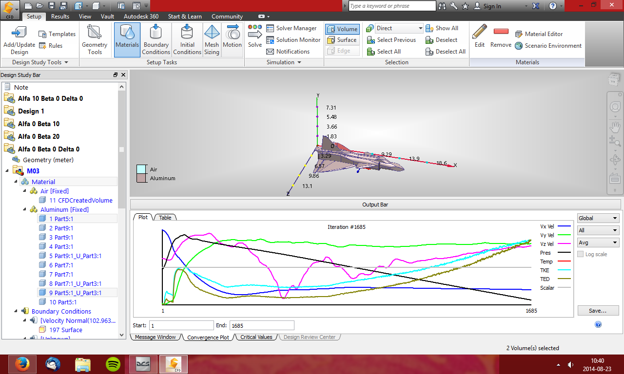
Message 16 of 16
08-25-2014
06:19 PM
- Mark as New
- Bookmark
- Subscribe
- Mute
- Subscribe to RSS Feed
- Permalink
- Report
08-25-2014
06:19 PM
Hi!
You might want to review some of the setup options discussed in this forum discussion:
Best regards,
Royce.Abel
Technical Support Manager
Reply
Topic Options
- Subscribe to RSS Feed
- Mark Topic as New
- Mark Topic as Read
- Float this Topic for Current User
- Bookmark
- Subscribe
- Printer Friendly Page
Forums Links
Can't find what you're looking for? Ask the community or share your knowledge.
Post to forums
