Community
CFD Forum
Welcome to Autodesk’s CFD Forums. Share your knowledge, ask questions, and explore popular CFD topics.
Turn on suggestions
Auto-suggest helps you quickly narrow down your search results by suggesting possible matches as you type.
Reply
Topic Options
- Subscribe to RSS Feed
- Mark Topic as New
- Mark Topic as Read
- Float this Topic for Current User
- Bookmark
- Subscribe
- Printer Friendly Page
Message 1 of 27
10-18-2013
12:31 AM
- Mark as New
- Bookmark
- Subscribe
- Mute
- Subscribe to RSS Feed
- Permalink
- Report
10-18-2013
12:31 AM
Natural ventilation
Hello,
I am an architecture student, and I am working on a passive cooling, naturally ventilated design. I am still a beginner with Simulation CFD. I was trying to see what my options are with my project. I basically want to simulate how the air enters the room from the outside, how it moves inside and how the temperature changes. I know it sounds pretty simple. Are there any videos or tutorials to help with that? Question 2, does Simulation CFD use weather files or do I always have to specify the weather conditions and so.
26 REPLIES 26
Message 2 of 27
10-18-2013
02:31 AM
- Mark as New
- Bookmark
- Subscribe
- Mute
- Subscribe to RSS Feed
- Permalink
- Report
10-18-2013
02:31 AM
Hi,
You are going to need to set this up using CFD Boundary Conditions - what is usually contained within weather files?
Best bet is to model the building on the ground and also add an air-volume around it - then you can apply flow and temperaure conditions to the inlet and a P=0 at the outlet of the air volume (to let the air escape again).
This would be a good starting point I think.
Kind regards,
Jon
Jon Wilde
Technical Support Manager
CFD Knowledge Network | CFD Help | My Screencasts | Autodesk Simuation YouTube | CFD Tutorials
Message 3 of 27
10-18-2013
08:08 AM
- Mark as New
- Bookmark
- Subscribe
- Mute
- Subscribe to RSS Feed
- Permalink
- Report
10-18-2013
08:08 AM
Thank you for your prompt response. I'll start with this today and I will see where I get and I will ask again if I get stuck with something.
Weather files are basically used for energy simulation software such as eQuest. Let's say that for example I want to simulate a building in San Diego, CA. all I have to do is to import the weather file which contains all the climatic data for San Diego through out the year and the software would use it to smulate different designs, So you wouldn't need to specify any climatic conditions and the software would give you results for the different months/days/hours.
Thanks again
Message 4 of 27
10-18-2013
10:01 AM
- Mark as New
- Bookmark
- Subscribe
- Mute
- Subscribe to RSS Feed
- Permalink
- Report
10-18-2013
10:01 AM
Ah OK, makes sense.
Just be sure to start simple - steady state only, no radiation and then go from there once that is working.
Feel free to post some images of the setup/results if you need more help.
Jon Wilde
Technical Support Manager
CFD Knowledge Network | CFD Help | My Screencasts | Autodesk Simuation YouTube | CFD Tutorials
Message 5 of 27
10-24-2013
08:43 PM
- Mark as New
- Bookmark
- Subscribe
- Mute
- Subscribe to RSS Feed
- Permalink
- Report
10-24-2013
08:43 PM
Hello again,
I would appreciate your help answering a few questions. I just need to know if Simulation CFD has the potential of doing what I'm going to show and if you could give me a few tips.
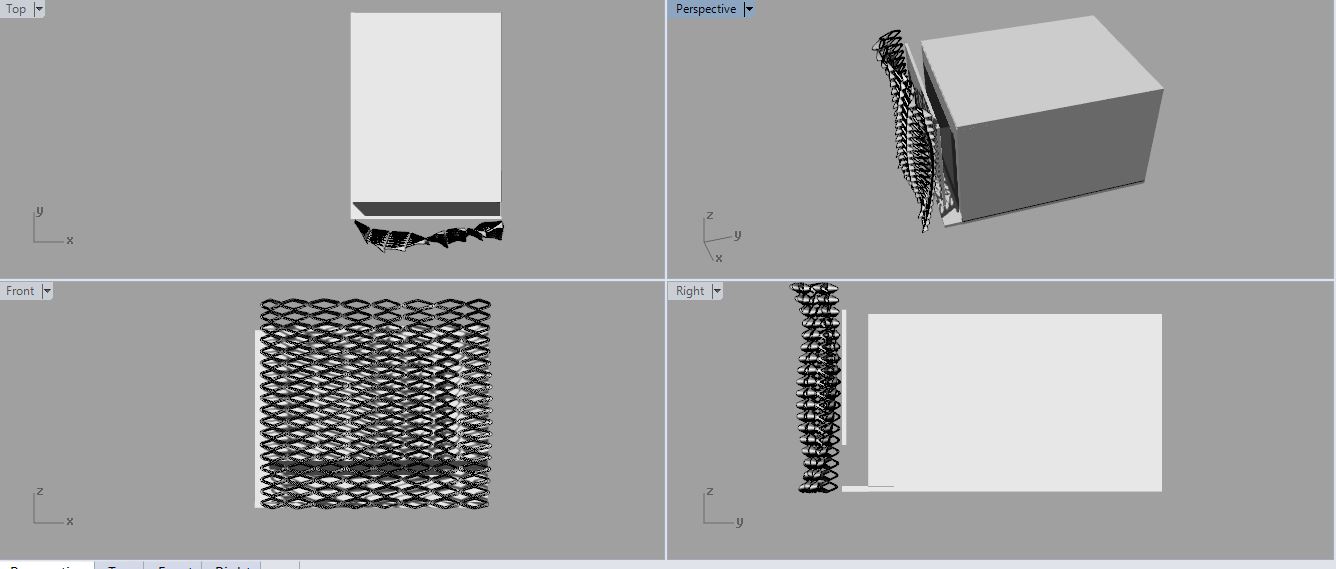
Image number one shows simplified drawings of what I am working on. a small space that is naturally ventilated, with an out door air inlet and outlet. I have a facade system I am working on, which consists of a perforated external skin and a glazed layer behind it.
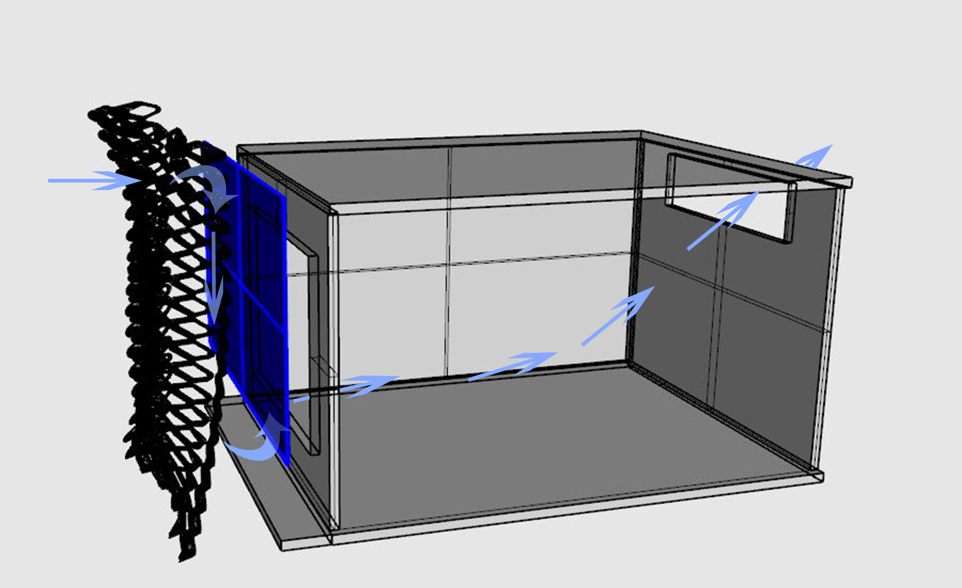
Image number 2 shows how the air is expected to move considering that the top and bottom between the building and the skin are blocked). The air is going to penetrate through the external skin, move down towards the opening to go up again towards the window and leave the space from the outlet).
What I need to do is to study the air flow and speed, change in temperature, and thermal comfort inside the space. Would that be possible? Can you give me some tips please?
I would really appreciate your help as I am kind of stuck with this.
Thank you!
Message 6 of 27
10-24-2013
08:43 PM
- Mark as New
- Bookmark
- Subscribe
- Mute
- Subscribe to RSS Feed
- Permalink
- Report
Message 7 of 27
10-24-2013
10:10 PM
- Mark as New
- Bookmark
- Subscribe
- Mute
- Subscribe to RSS Feed
- Permalink
- Report
10-24-2013
10:10 PM
Dear Architect,
Based on your previous post and uploaded images, Yes you can determine "air flow and speed, change in temperature, and thermal comfort inside the space" but as a beginner, you can take this(Solve) as a 3 case:
1. Fluid Flow - to know air flow & speed inside occupant space
2. Fluid Flow + Heat Trasnfer - to additionally find, delta Temperature
3. Fluid Flow + Heat Transfer + Radiation - additionally, to extract weather conditions, solar loading & to extract thermal comfort.
Do, each step exclusively and understand it & proceed further. By completion of all 3 seperate steps you will be confident of using all together & know how simple to use this Tool.
All d best.
Regards,
Ajay.S
Message 8 of 27
10-24-2013
10:38 PM
- Mark as New
- Bookmark
- Subscribe
- Mute
- Subscribe to RSS Feed
- Permalink
- Report
10-24-2013
10:38 PM
Thank you so much for your prompt response. I just want to make sure that the software will be satisfying my needs before I start working on it. I also want to ask one last question before I start; let's say that I have a water medium or moisturised medium on the external skin, would the software also determine the change in temperature after the air penetrates through this moisturised medium? To simplify the question please look at the image attached with this message.
Thank you so much again and your help is much appreciated.
Message 9 of 27
10-24-2013
10:53 PM
- Mark as New
- Bookmark
- Subscribe
- Mute
- Subscribe to RSS Feed
- Permalink
- Report
10-24-2013
10:53 PM
Dear,
These links can be of much help,
http://help.autodesk.com/view/SCDSE/2014/ENU/
My suggestion, is to start working with the Tool and explore your requirment, its very simple to use and understand.
All the best.
Kind Regards,
Ajay.S
Message 10 of 27
10-24-2013
10:55 PM
- Mark as New
- Bookmark
- Subscribe
- Mute
- Subscribe to RSS Feed
- Permalink
- Report
10-24-2013
10:55 PM
Wonderful. I did play with it a bit and explored a few stuff but just waned to make sure. Thank you so much sir and I ppreciate your efforts.
Message 11 of 27
10-24-2013
11:15 PM
- Mark as New
- Bookmark
- Subscribe
- Mute
- Subscribe to RSS Feed
- Permalink
- Report
10-24-2013
11:15 PM
Dear,
No worries.
All the best for your projects.
Regards,
Ajay.S
MICROGENESIS, INDIA
Message 12 of 27
11-14-2013
12:08 PM
- Mark as New
- Bookmark
- Subscribe
- Mute
- Subscribe to RSS Feed
- Permalink
- Report
11-14-2013
12:08 PM
Hello again,
I finished my design and I'm done with my model as well and want to make
sure I get it right when I import it to Simulation CFD. I'm going to
simulate a room (simple 4 walls and a window), the building envelope has a
building skin that has shading devices and glass layers. I tried importing
the geometry and it gave me so many surfaces on each of the walls. Would it
be better if I import it as surfaces (without thicknesses for the walls and
elements)?
Please let me know so I can start the simulation 🙂
Thank you so much again
Message 13 of 27
11-19-2013
12:20 AM
- Mark as New
- Bookmark
- Subscribe
- Mute
- Subscribe to RSS Feed
- Permalink
- Report
11-19-2013
12:20 AM
OK. I figured this part out. I am sorry if I am sending a lot. I just want to make sure I'm doing everything right. I have 2 small questions:
1- I have a room of 4 walls, How can I make 3 of these walls adiabatic ( I don't want any heat transfer from the outside or any effects to happen through them).
2- Let's say that my walls consist of many layers, when assigning the material, does it matter which material I assign to the wall If I enter the film coefficient for the whole wall? Or do I have to import all the wall layers and assign the materials to each one of them?
I appreciate your prompt response.
Message 14 of 27
11-19-2013
01:54 PM
- Mark as New
- Bookmark
- Subscribe
- Mute
- Subscribe to RSS Feed
- Permalink
- Report
11-19-2013
01:54 PM
Hi,
1) Unless you have air or a film coeff on the outside of the walls, they will be adiabatic
2) A film coeff is typically used to specify the heat transferred from the solid to the external air. You might be better off creating a material that combines all of the layers into one (much like our PCB calculator), taking the conductivity and thickness of each and using the ratio of that vs the overall thickness to form one material. Might save a bit of time, ensure you have at least 2 elements through any material thickness to properly capture the heat transfer.
Kind regards,
Jon
Jon Wilde
Technical Support Manager
CFD Knowledge Network | CFD Help | My Screencasts | Autodesk Simuation YouTube | CFD Tutorials
Message 15 of 27
11-19-2013
04:38 PM
- Mark as New
- Bookmark
- Subscribe
- Mute
- Subscribe to RSS Feed
- Permalink
- Report
11-19-2013
04:38 PM
For point 1, what If I had air outside the walls. I just need the interaction to be with 1 wall, not the others.
for point 2, The case is I have is a typical wall that consists of steel studs, gypsum board, cladding and insulation, I would be importing the wall as 1 layer to the sim software, would it be ok if I assign one material to the wall and specifiy the film coefficient to what is equal to the U value of all the layers?
Thak you again.
Message 16 of 27
12-03-2013
04:35 PM
- Mark as New
- Bookmark
- Subscribe
- Mute
- Subscribe to RSS Feed
- Permalink
- Report
12-03-2013
04:35 PM
Hello,
I am really disparate for some help here. I assigned all the materials and the boundary conditions. It keeps telling me I have a problem with the mesh. I made sure the model is done right 100 time and made sure all parts are fine. I tried fining and coarsening many parts with no result. I am trying to attach a copy of the work but it's 12 mb in size. Whenever I try to preview the mesh the software shutsdown.
I am using sim 360 for simulation and it's a pretty small project, a room. I am really disappointed I was counting on the software but it has given me lots of problems.
Message 17 of 27
12-03-2013
04:36 PM
- Mark as New
- Bookmark
- Subscribe
- Mute
- Subscribe to RSS Feed
- Permalink
- Report
Message 18 of 27
12-03-2013
06:26 PM
- Mark as New
- Bookmark
- Subscribe
- Mute
- Subscribe to RSS Feed
- Permalink
- Report
12-03-2013
06:26 PM
Sometimes I get that error when there are small gaps/issues with my design. Try the surface refinement + gap refinement tool in the auto meshing window. Usually does the trick for me.
Message 19 of 27
12-04-2013
01:46 AM
- Mark as New
- Bookmark
- Subscribe
- Mute
- Subscribe to RSS Feed
- Permalink
- Report
12-04-2013
01:46 AM
If that fails, please pm me and I will grab the CFZ file for a quick health check.
Have you already run through the training material?
Kind regards,
Jon
Jon Wilde
Technical Support Manager
CFD Knowledge Network | CFD Help | My Screencasts | Autodesk Simuation YouTube | CFD Tutorials
Message 20 of 27
12-04-2013
09:01 AM
- Mark as New
- Bookmark
- Subscribe
- Mute
- Subscribe to RSS Feed
- Permalink
- Report
12-04-2013
09:01 AM
I tried the gap and edge refinement but it doesn't seem to be working. I know I have a lot of
curvy' forms in the model, I tried to supress them as well but it's not working. The file is almost 10 mb in size and it's not letting me post it here. I would really appreciate any help.
Reply
Topic Options
- Subscribe to RSS Feed
- Mark Topic as New
- Mark Topic as Read
- Float this Topic for Current User
- Bookmark
- Subscribe
- Printer Friendly Page
