Community
CFD Forum
Welcome to Autodesk’s CFD Forums. Share your knowledge, ask questions, and explore popular CFD topics.
Turn on suggestions
Auto-suggest helps you quickly narrow down your search results by suggesting possible matches as you type.
Reply
Topic Options
- Subscribe to RSS Feed
- Mark Topic as New
- Mark Topic as Read
- Float this Topic for Current User
- Bookmark
- Subscribe
- Printer Friendly Page
Message 1 of 11
03-25-2014
10:49 AM
- Mark as New
- Bookmark
- Subscribe
- Mute
- Subscribe to RSS Feed
- Permalink
- Report
03-25-2014
10:49 AM
Hello,
I am new to CFD Simulation.
I have an assembly, a nozzle head (with 4 inlet surfaces), and a filter section (outlet) and I am trying to simulate the airflow in the room to see the flow distribution.
I assigned Boundary Conditions (volumetric flow rate-fully developed) to the inlets, and a static gage pressure of 0 at the outlet.
I supressed he solid objects, meshed the air volume and ran the simulation.
I am getting incredibly high velocities (to the 6th power), and it looks like there is one small section (where the filter meets the nozzle head) that the high velocities are. Also, I solved it using flow and the default settings (ADV1) for 750 iterations.
I took a look at the Summary File, and I have:
Total Mass flow in: 4.26 lbm/s
Total Mass flow out: 1120.67 lbm/s
How can I fix this?
Solved! Go to Solution.
Solved by ssenbore. Go to Solution.
10 REPLIES 10
Message 2 of 11
03-25-2014
12:22 PM
- Mark as New
- Bookmark
- Subscribe
- Mute
- Subscribe to RSS Feed
- Permalink
- Report
03-25-2014
12:22 PM
Is it possible for you to share a screenshot of the overall model and where the high velocities are located?
Thanks!
Royce.Abel
Technical Support Manager
Message 3 of 11
03-25-2014
12:59 PM
- Mark as New
- Bookmark
- Subscribe
- Mute
- Subscribe to RSS Feed
- Permalink
- Report
03-25-2014
12:59 PM

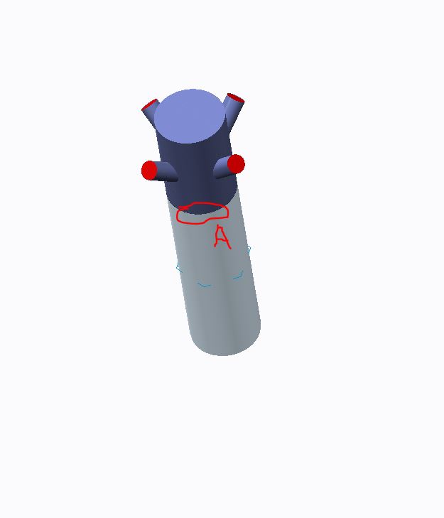
They red circles are the flow inlets, the gray cylinder is the outlet (at 0 psi gage static pressure), the 4 nozzles are radially symmetric (and the gray and blue cylinders as well). The setup is in the middle of the air volume.
The high velocities (usually 4-7 million in/s) occur at the location marked A (and this high velocity does not occur on the other side).

If this second shot helps, I am in the middle of running another sim with the same model, and its showing the velocity vectors. This is only iteration 250/750. But as you can see, the velocity distribution around the middle where the top and bottm parts meet is not uniform.
Thanks for your help, any insight is appreciated.
Message 4 of 11
03-26-2014
06:39 AM
- Mark as New
- Bookmark
- Subscribe
- Mute
- Subscribe to RSS Feed
- Permalink
- Report
03-26-2014
06:39 AM
Are you modeling the walls as surface materials? If you PM me the model I can take a closer look, just send me a download link from dropbox or A360.
Royce.Abel
Technical Support Manager
Message 5 of 11
03-26-2014
08:47 AM
- Mark as New
- Bookmark
- Subscribe
- Mute
- Subscribe to RSS Feed
- Permalink
- Report
03-26-2014
08:47 AM
From a cursory observation, I think this is a case of divergence.
Have you tried reducing the factors in Solve Dialogue box >> Solution Control to 0.3 from 0.5?
Also I have seen divergences in very coarse and bad meshes. Make sure you have fine enough mesh to capture the flow physics and gradients.
Message 6 of 11
03-26-2014
08:52 AM
- Mark as New
- Bookmark
- Subscribe
- Mute
- Subscribe to RSS Feed
- Permalink
- Report
03-26-2014
08:52 AM
Here is the link to the archive file.
https://www.dropbox.com/s/enkm0c21iu382lu/Hospital%20Room%20Circulation2.cfz
https://www.dropbox.com/s/enkm0c21iu382lu/Hospital%20Room%20Circulation2.cfz
Message 7 of 11
03-26-2014
09:00 AM
- Mark as New
- Bookmark
- Subscribe
- Mute
- Subscribe to RSS Feed
- Permalink
- Report
03-26-2014
09:00 AM
I think you are right about divergence. Sometimes the solver quits and gives that error.
I have not yet tried your suggestion regarding the solution control.
Regarding the mesh, the mesh I used most recently is below (the spot where the high velocities occur is at the location where the top part meets the bottom part. No Interference from the CAD model, no gap between the parts, and the high velocity region is not radially symmetric, even though the model is).
Is that a bad mesh?

Message 8 of 11
03-26-2014
09:58 AM
- Mark as New
- Bookmark
- Subscribe
- Mute
- Subscribe to RSS Feed
- Permalink
- Report
03-26-2014
09:58 AM
I tried reducing the solve factors for Velocity, Pressure, Turbulence and Density to 0.3 and this time he solver stopped at 132 iterations due to divergence. Velocities were around 10^18 in/s
Message 9 of 11
03-27-2014
06:50 AM
- Mark as New
- Bookmark
- Subscribe
- Mute
- Subscribe to RSS Feed
- Permalink
- Report
03-27-2014
06:50 AM
The problem has been resolved!
According to this forum post http://forums.autodesk.com/t5/Simulation-CFD/Periodic-Boundary-divergence/m-p/3899665 I changed Advection scheme to ADV 5 (I had previously been using ADV 1 and 2), and with ADV 5, the solver detected convergence around 400 iterations, and the velocities were much more reasonable (~1500 in/s) and the mass flow rates were within the same order of magnitude, and the phantom spot with high velocities where both parts met also disappeared.
Thanks all!!
Message 10 of 11
03-27-2014
04:41 PM
- Mark as New
- Bookmark
- Subscribe
- Mute
- Subscribe to RSS Feed
- Permalink
- Report
03-27-2014
04:41 PM
I wanted to get into more detail about this one, but ADV5 is a potential solution, but might not help in all cases here.
What you have going on here is a case where the 0 pressure boundary condition is very much within the flow domain. In general is a bad idea. The solver expects that the flow is fairly developed before it goes into the 0 pressure. This is why in the help we suggest to have inlet and outlet extension and really emphisize the outlet extension. The inlet extention is also a good idea so that a better mesh can be formed on the inlet face, the small duct helps better define mesh enhancement layers at the inlet face.
So, where does the air go when it goes through the 0 pressure boundary condition? Could the CAD be altered in such a way that we can duct that air out somehow?
ADV5 because of the tighter numerical methods will have the most potential to be stable in this sort of situation. Adjusting the solutions controls might have helped or more likely it will just delay the onset of the divergence.
Some extended thoughts. When solving with the k-e turbulence model you should limit your usage of mesh enhancement to between 3-5 layers. Using 10 layers is overkil, especially for this type of analysis. Keep the layer factor at 0.45.
Best regards,
Royce.Abel
Technical Support Manager
Message 11 of 11
03-28-2014
09:04 AM
- Mark as New
- Bookmark
- Subscribe
- Mute
- Subscribe to RSS Feed
- Permalink
- Report
03-28-2014
09:04 AM
Thanks for your reply.
The 0 pressure boundary condition is a filter system that cleans the air while the nozzles spew out clean air into the room. What happens inside the filter system I am not aware of, so I don't know that it is possible to move the 0 pressure BC away from the flow domain.
Adjusting the solutions controls using ADV 1 just delayed the onset of divergence.
Thanks for the tip on Mesh Enhance enhancement using the k-e turbulence model.
Shayee Senbore
Technical Specialist
Boundary Systems
O: 440-274-0291x316 | C:216-538-3397
Skype: shayee.senbore
www.boundarysys.com
www.creoracing.com
[Description: Description: C:\Users\Ndarhinger\Desktop\Graphics\Facebook-Icon.png][Description: Description: C:\Users\Ndarhinger\Desktop\Graphics\Twitter-Icon.png][Description: Description: linkedin][Description: Description: C:\Users\Sales\Desktop\youtube.png]
[cid:image006.jpg@01CF4A7D.B0C85480]
Reply
Topic Options
- Subscribe to RSS Feed
- Mark Topic as New
- Mark Topic as Read
- Float this Topic for Current User
- Bookmark
- Subscribe
- Printer Friendly Page
