Community
CFD Forum
Welcome to Autodesk’s CFD Forums. Share your knowledge, ask questions, and explore popular CFD topics.
Turn on suggestions
Auto-suggest helps you quickly narrow down your search results by suggesting possible matches as you type.
Reply
Topic Options
- Subscribe to RSS Feed
- Mark Topic as New
- Mark Topic as Read
- Float this Topic for Current User
- Bookmark
- Subscribe
- Printer Friendly Page
Message 1 of 10
Anonymous
2301 Views, 9 Replies
03-29-2013
04:19 PM
- Mark as New
- Bookmark
- Subscribe
- Mute
- Subscribe to RSS Feed
- Permalink
- Report
03-29-2013
04:19 PM
Intake Manifold Simulation
Hello,
I'm currently doing a university project lookung at a variable intake manifold, specifically the airflow inside.
Is it possible to use SimulationCFD to create the scenario where it takes into consideration valve opening at the ends of outlet pipes and air rushes out and the pipes need to be refilled?
Thanks for your time.
Cheers,
David
9 REPLIES 9
Message 2 of 10
03-29-2013
05:09 PM
- Mark as New
- Bookmark
- Subscribe
- Mute
- Subscribe to RSS Feed
- Permalink
- Report
03-29-2013
05:09 PM
Sounds straightforward. Is the valve stationary? A picture of your manifold (or even handsketch) can be helpful here in understanding your exact problem.
OJ
Message 3 of 10
03-30-2013
02:52 AM
- Mark as New
- Bookmark
- Subscribe
- Mute
- Subscribe to RSS Feed
- Permalink
- Report
03-30-2013
02:52 AM
Not quite, in the video link attached, FSAE Intake Manifold CFD Transient Simulation (velocity), is the kind of thing I want to do. The difference with mine is that the position of the start of the 4 runners changes with slots in the large pipe can be changed (similar to BMW's DIVA system - Intake and Exhaust,)so I need to take into account that it would be connected to a car engine which would suck air out at given intervals, if that makes sense.
I've never done this before so any advice on how to do this would be great help (had a look at the tutorials but can't really see which ones would be useful)
Cheers,
David
Message 4 of 10
03-30-2013
06:12 PM
- Mark as New
- Bookmark
- Subscribe
- Mute
- Subscribe to RSS Feed
- Permalink
- Report
03-30-2013
06:12 PM
Are the four ducts inlets or outlets? Is the left/right boundary inlet/outlet? Do inlets open in transient manner or do outlets do?
OJ
Message 5 of 10
03-30-2013
06:27 PM
- Mark as New
- Bookmark
- Subscribe
- Mute
- Subscribe to RSS Feed
- Permalink
- Report
03-30-2013
06:27 PM
OJ,
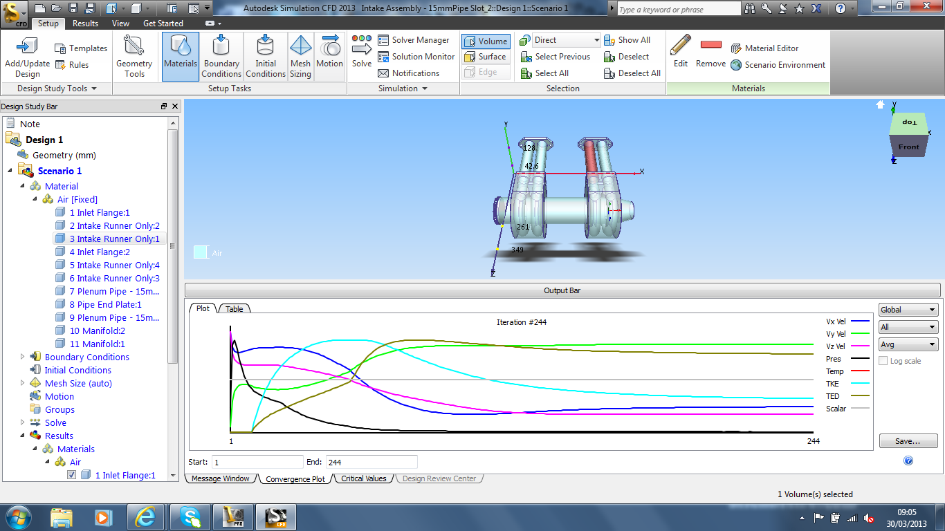
The four ducts are outlets and the right hand side youas you look at the screen dump, the tapered end, is the inlet.
When you say transient, I assume you mean the representation of valves opening and closing then they are at the end of the four outlet ducts. Hope this helps define my situation a bit better and thanks for your interest.
Cheers,
David
Message 6 of 10
03-31-2013
08:26 AM
- Mark as New
- Bookmark
- Subscribe
- Mute
- Subscribe to RSS Feed
- Permalink
- Report
03-31-2013
08:26 AM
This is interesting, and am always happy to help. I have seen the video you posted, along with a similar video but using pressure contours, which was more useful in the sense that you can always spot backpressures at outlet as an indication of valves closing etc. From what I understand, there is a left inlet which injects fluid with periodically. The four bottom outlets have valves that open and close in a definitive sequence.
Coming to your problem, here is a thought. You can give your inlet boundary condition as transient boundary condition by defining it as a piecewise linear function (using a table etc) so flow is on and off at a frequency in of your inlet mass flow bursts.
Outlets will be tricky. One way could be to alternate between pressure outlet and wall periodically, but not sure if you can do this in SimCFD.
A long shot: You can also use axial closing valve at the end of every duct and use the motion of analysis. There is a tutorial (axial valve) which should guide you through the setup. Here, define the outlet as transient boundary condition alternating between zero pressure and very high pressure with the corresponding valve cycle in your mechanism. Arrange the valves inside the ducts such that as soon as outlet pressure reaches high, it shuts the valve, pushing inside, and fluid flow stops. Thus, when outlet pressure is zero, valve is open, fluid goes out. When outlet pressure is high, valve closes and fluid can't escape.
Not an elegant way I know, but can't think of anything else as of now 🙂
OJ
Message 7 of 10
03-31-2013
08:50 AM
- Mark as New
- Bookmark
- Subscribe
- Mute
- Subscribe to RSS Feed
- Permalink
- Report
03-31-2013
08:50 AM
Thanks again for your reply OJ,
You're assesment of the video is spot and that difinitive sequence is exactly what I'm trying to emulate.
The axial valve is a good idea, but unfortunately the valve sequencing is very important to highlight any design flaws, if SimCFD is unable to facilitate this then I may have to look at something like Ricardo-Wave.
Thanks again for your advice.
Cheers,
David
Message 8 of 10
04-04-2013
03:24 PM
- Mark as New
- Bookmark
- Subscribe
- Mute
- Subscribe to RSS Feed
- Permalink
- Report
04-04-2013
03:24 PM
David,
The trick here is to both vary the pressure at each manifold outlet and also ensure that each outlet is truly closed when the valves are shut. From my FSAE days, I followed the following procedure:
- Create a transient pressure boundary condition for each outlet. This BC will impart a negative pressure during the time when the valve is open. You may have data on what typical pressure profiles are at this point in the runner versus time.
- Add a solid disk (a short cylinder) to each outlet. This object should be larger than the diameter of the outlet, and have a height which is greater than the local mesh size at the outlet.
- Position the disk in cad an abritary distance away from the outlet. One inch is fine.
- Apply a motion condition to each disk so that it moves upwards and interferes completely with each runner when the valve is supposed to be fully closed. This will effectively close off the port and dissallow flow backwards into the runner. Without the physical blockage, the boundary condition alone will not prevent flow.
It's a little ghetto, but it works well and is relatively easy to pull off.
Hope that helps!
James
James C. Neville
Technical Specialist
Manufacturing - Simulation
James C. Neville
Autodesk Consulting
Autodesk Consulting
Message 9 of 10
Anonymous
in reply to:
Anonymous
04-09-2013
04:53 AM
- Mark as New
- Bookmark
- Subscribe
- Mute
- Subscribe to RSS Feed
- Permalink
- Report
04-09-2013
04:53 AM
Hi James,
Thanksfor your reply, I'm having a go following your suggestions; unfortunately I'm a complete newby at this![]()
What should I do about pressure profile values if I don't have any?
How do you setup the motion of the valves?
When it comes to running the solve function,do you set it up as a transient scenario and what type should it be? (I've calculated when the valve should be open over 4 revolutions if this helps - see attached Excel file).
Thanks for your input.
Cheers,
David
Message 10 of 10
05-15-2013
03:14 PM
- Mark as New
- Bookmark
- Subscribe
- Mute
- Subscribe to RSS Feed
- Permalink
- Report
05-15-2013
03:14 PM
Hi James,
Thanks for the advice; when you set the boundary conditions in your example, did you set initial conditions to, or did you just run with the BC?
Cheers,
David
Thanks for the advice; when you set the boundary conditions in your example, did you set initial conditions to, or did you just run with the BC?
Cheers,
David
Reply
Topic Options
- Subscribe to RSS Feed
- Mark Topic as New
- Mark Topic as Read
- Float this Topic for Current User
- Bookmark
- Subscribe
- Printer Friendly Page
Forums Links
Can't find what you're looking for? Ask the community or share your knowledge.
Post to forums
