Community
- Forums Home
- >
- CFD Community
- >
- CFD Forum
- >
- Re: How to simulate pressure build-up in DGS CFD simulation
CFD Forum
Welcome to Autodesk’s CFD Forums. Share your knowledge, ask questions, and explore popular CFD topics.
Turn on suggestions
Auto-suggest helps you quickly narrow down your search results by suggesting possible matches as you type.
Reply
Topic Options
- Subscribe to RSS Feed
- Mark Topic as New
- Mark Topic as Read
- Float this Topic for Current User
- Bookmark
- Subscribe
- Printer Friendly Page
Message 1 of 4
11-05-2013
01:15 PM
- Mark as New
- Bookmark
- Subscribe
- Mute
- Subscribe to RSS Feed
- Permalink
- Report
11-05-2013
01:15 PM
How to simulate pressure build-up in DGS CFD simulation
Hi,
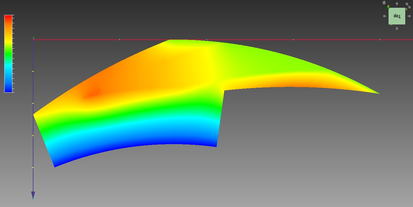
I’m student and I use CFD 2013 to simulate pressure distribution in gas-dynamic layer of spiral grooved dry gas seal, what is a part of my engineer diploma project. Videos introducing topic:
http://www.youtube.com/watch?v=galIfq9SVEo
http://www.youtube.com/watch?v=jrGUyqaLAaM
Using periodic BC I simulate only 1/12th of entire ring. Main problem and the reason I’m asking for help/advice is angular motion of rotating(mating) ring which cause proper pressure build-up and lift-off effect. It may be important: I use constant volume -> I set the gas layer height in model(Inventor) and then simulate pressure distribution.
I’ve tried 3 possibilities(models are attached in pdf):
1) Angular velocity BC (1 volume model)
2) Rotating region (3 volume model-> I’ve tried to follow centrifugal pump tutorial)
3) Motion (2 volume model)
Ad 1) It’s the only model that gave my so far any results(not the best but quite satisfying) but I’m not sure about it because of such note on help.autodesk: “This condition does not induce flow caused by rotation…” -> maybe because of that pressure distribution is lower than experimental results?
Ad 2) What happens is: “… Solver has exited unexpectedly”, just after such statements:
Calculating BC data structures… -> Loading results phase 4 of 5-> error
In another topic I’ve read that it may be caused by insufficient RAM, but it happens even with reduced number of elements.
Ad 3) very disappointing results(may be caused by wrong settings?)
Finally, after long introduction I may ask for you help/advice:
Which model is the most suitable for such simulation?
What are the tricky things I should especially pay attention to during that simulation?
*I’ve also attached sample of results by model 1) to visualize how it should look like.
Thanks in advance for any response.
3 REPLIES 3
Message 2 of 4
11-06-2013
01:57 AM
- Mark as New
- Bookmark
- Subscribe
- Mute
- Subscribe to RSS Feed
- Permalink
- Report
11-06-2013
01:57 AM
Hi,
Thanks for the detail here, pretty complex model by the looks of things.
If you can get it working, then the periodic approach would be great - it looks like this is working the best so far.
A rotating region (RR) needs to include the full 360 deg model and so should the motion to be able to achieve anything like the correct results.
You best bet would appear to be to run the full 360deg model with an RR or stick with the BC approach.
Jon Wilde
Technical Support Manager
CFD Knowledge Network | CFD Help | My Screencasts | Autodesk Simuation YouTube | CFD Tutorials
Message 3 of 4
11-06-2013
10:24 AM
- Mark as New
- Bookmark
- Subscribe
- Mute
- Subscribe to RSS Feed
- Permalink
- Report
11-06-2013
10:24 AM
Hi,
Thanks for pointing the 360deg issue, I’ve already started investigating the full model simulation.
In case of ring with 12 spiral grooves, I guess it would be better to match them with thin layer(taken from gas layer volume according to previously attached drawing) into one rotating region, rather than making it 12 rotating region simulation? It would then consist of 3volumes: static fluid layer, rotating region(grooves + thin layer), solid mating ring.
By saying that I can stick to rotational velocity BC model, you suggest that it is physically correct? So it’s my misinterpretation to worry about that note in help.autodesk about rotational velocity BC: “This condition does not induce flow caused by rotation…”?
I’m not sure about another note: Each rotating object must be completely immersed in a rotating region. In my case if I multiple rotating region model(previously attached drawing) and match grooved volumes with mentioned above thin layer; mating ring won’t be immersed in rotating region but will just contact it by one side. Is it still correct?
Thanks,
jbadura
Message 4 of 4
11-06-2013
10:31 AM
- Mark as New
- Bookmark
- Subscribe
- Mute
- Subscribe to RSS Feed
- Permalink
- Report
11-06-2013
10:31 AM
Hi jbadura,
I think it might be wise for you to take a look at this guide on pumps and how to implement rotating regions. Really there should just be one region, encompassing all moving parts - it's axis must be the axis of rotation. Best to have it's edge 1/2 way inbetween the rotor at the static wall. It must only encase the moving parts, nothing static. I think this is possible, looking at the images you provided.
Those notes are correct, my mistake, better to use a RR if you can but implement it properly and hopefully the guide will enable you to do so.
Kind regards,
Jon
Jon Wilde
Technical Support Manager
CFD Knowledge Network | CFD Help | My Screencasts | Autodesk Simuation YouTube | CFD Tutorials
Reply
Topic Options
- Subscribe to RSS Feed
- Mark Topic as New
- Mark Topic as Read
- Float this Topic for Current User
- Bookmark
- Subscribe
- Printer Friendly Page

%20ring%20side.jpg)