Community
CFD Forum
Welcome to Autodesk’s CFD Forums. Share your knowledge, ask questions, and explore popular CFD topics.
Turn on suggestions
Auto-suggest helps you quickly narrow down your search results by suggesting possible matches as you type.
Reply
Topic Options
- Subscribe to RSS Feed
- Mark Topic as New
- Mark Topic as Read
- Float this Topic for Current User
- Bookmark
- Subscribe
- Printer Friendly Page
Message 1 of 2
Anonymous
311 Views, 1 Reply
11-15-2013
02:42 PM
- Mark as New
- Bookmark
- Subscribe
- Mute
- Subscribe to RSS Feed
- Permalink
- Report
11-15-2013
02:42 PM
Cannot get thermal distribution
I am kind of new to Autodesk tools. I want to simulate thermal distribution over a smartphone and we built very simple model for that.
I used Autodesk Inventor Pro to each component as a part (.ipt) and assemble them as a mold design file (.iam). Then I launched Simulation CFD and created a study pointing to the .iam file.
I am managed to assign materials for every components and specify the heat generation to IC chips.
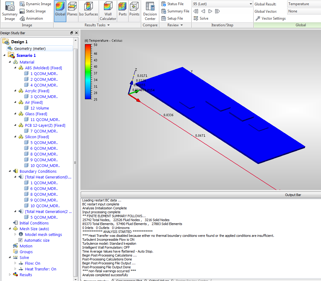
Then I adopted automatic mesh size and clicked "solve". It solves within 1 minutes (it seems to be too fast... the simulation setup are shown in the right side of the figure) to give results. However, I am not able to see any thermal distribution on my device. Even the IC chips I assigned heat generation stay at 25C (the small blocks in figure are IC chips).
Since the smartphone is a closed case, I didn't specify any inlet and outlet air. Could this be the problem? I set the volume inside the device to be air.
Could anyone help? Thanks a lot.
1 REPLY 1
Message 2 of 2
11-18-2013
01:16 AM
- Mark as New
- Bookmark
- Subscribe
- Mute
- Subscribe to RSS Feed
- Permalink
- Report
11-18-2013
01:16 AM
Hi,
Do you have any reference to an ambient temperature anywhere? This is likely the issue.
There are 2 approaches here.
1) Run with air around your device and let CFD calculate the air flow and heat transfer to it - you would need Boundary Conditions (BC's) on the top surface of the air, assuming yout phone is on a bench of somesort. I would use P=0 and T=ambient.
2) Use film coefficients - faster but less accurate - on the external surfaces of the material. Something like 5W/m2/K at ambient temp would be a good start
Typically the auto mesh will be too coarse - ideally you need to aim for 4-5 elements within air gaps and 2 elements through thin solids.
You could also consider running with air_solid (a material you would need to create yourself) as the airlow will be so minimal, you could assume conduction only and rule out any convection internally. This means we would not add a boundary layer to the fluid mesh, meaning a faster run time.
Hope that helps.
Kind regards,
Jon
Jon Wilde
Technical Support Manager
CFD Knowledge Network | CFD Help | My Screencasts | Autodesk Simuation YouTube | CFD Tutorials
Reply
Topic Options
- Subscribe to RSS Feed
- Mark Topic as New
- Mark Topic as Read
- Float this Topic for Current User
- Bookmark
- Subscribe
- Printer Friendly Page
