Community
- Forums Home
- >
- Robot Structural Analysis Products Community
- >
- Robot Structural Analysis Forum
- >
- Re: Vertical Panels
Robot Structural Analysis Forum
Welcome to Autodesk’s Robot Structural Analysis Forums. Share your knowledge, ask questions, and explore popular Robot Structural Analysis topics.
Turn on suggestions
Auto-suggest helps you quickly narrow down your search results by suggesting possible matches as you type.
Reply
Topic Options
- Subscribe to RSS Feed
- Mark Topic as New
- Mark Topic as Read
- Float this Topic for Current User
- Bookmark
- Subscribe
- Printer Friendly Page
Message 1 of 14
01-13-2013
10:58 PM
- Mark as New
- Bookmark
- Subscribe
- Mute
- Subscribe to RSS Feed
- Permalink
- Report
01-13-2013
10:58 PM
Vertical Panels
Dear Colleagues
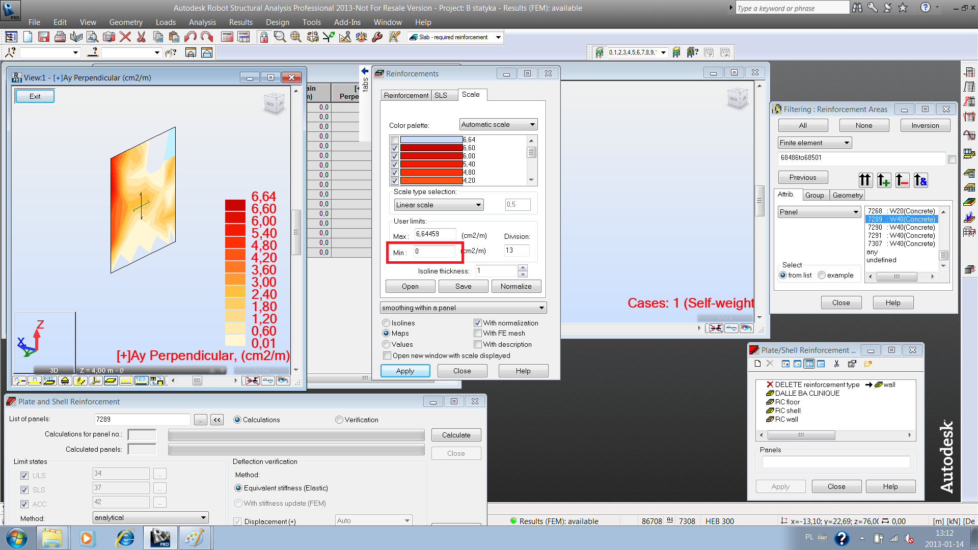
I faced a probem in the shear walls which I have chosen from the middle core of the building . As you see in the capture (1&2) , when I use “ analytical method “ sometimes a message appears saying that there is (unknow error for the panel) and the reinforcement appears to be not logical as appear in the capture (1) .
This case meet me in many vertical panels(walls) in the attached model.
Could you help me to overcome this problem ?
http://www.2shared.com/file/5yTRJtF4/Vertical_Panels.html
Note : If you send a captures for explanation , Kindly send it as attached.
Thanks in advance
Refaat
13 REPLIES 13
Message 2 of 14
01-14-2013
04:20 AM
- Mark as New
- Bookmark
- Subscribe
- Mute
- Subscribe to RSS Feed
- Permalink
- Report
01-14-2013
04:20 AM
As far as I can see the area of reinforcement cannot be calculated in one node of the panel. I think that you can use the results from the neighboring elements instead. The values of Ax(-) and Ax(+) are 0s therefore the map will not be displayed. In case you have the problem with other maps make sure the range of the scale is defined correctly.
If you find your post answered press the Accept as Solution button please. This will help other users to find solutions much faster. Thank you.
Artur Kosakowski
Message 3 of 14
01-15-2013
01:20 AM
- Mark as New
- Bookmark
- Subscribe
- Mute
- Subscribe to RSS Feed
- Permalink
- Report
01-15-2013
01:20 AM
Dear Artur
- Thanks , but I would like to know , what are the main causes for such type of messages "unknown error for the panel ".
- And how I can avoid in other models?
That is because I will not be able to submit my calculation report with such errors.
With Regards
Refaat
Message 4 of 14
01-15-2013
04:26 AM
- Mark as New
- Bookmark
- Subscribe
- Mute
- Subscribe to RSS Feed
- Permalink
- Report
01-15-2013
04:26 AM
- Thanks , but I would like to know , what are the main causes for such type of messages "unknown error for the panel ".
The reinforcement calculations is based on the iterative process. In the situations when for some reason this iterative process fails to converge this message is displayed.
- And how I can avoid in other models?
If this happens you may try to change meshing of the panel. If this fails all you can do is to report such situation and we have to investigate what actually caused the reinforcement calculation process to fail.
That is because I will not be able to submit my calculation report with such errors.
I think this should be possible. Having the results in all but one verification points (all centers of surface elements and all nodes but one) it is possible to estimate the value in the missing node from the neighboring results. As far as I can see it is also possible to display maps providing one enters the reasonable values of max and min values on the scale.
If you find your post answered press the Accept as Solution button please. This will help other users to find solutions much faster. Thank you.
Artur Kosakowski
Message 5 of 14
01-17-2013
01:12 AM
- Mark as New
- Bookmark
- Subscribe
- Mute
- Subscribe to RSS Feed
- Permalink
- Report
01-17-2013
01:12 AM
Dear Artur
After I investigated the case by changing the mesh (size -type) , I have noted that only in one situation the message ( Unknown error for panel ) is disappeared when I calculated the required reinforcement without included (ACC) cases.
Also, I have noted that when I included (ACC) but calculating the panel using one of the simplified method instead of analytical method, also the message is disappeared, but of course we can't use it in shear walls.
Based on above I can say that there is something to calculate the membrane forces during the seismic cases because even when I changed the used code (IBC2000&IBC2006&IBC2009 and UBC97) it gave the same scenario.
Note : Kindly take a look to the attached captures.
What can I do? , I am really worried from this problem .
Thanks for any assistance
Refaat
Message 6 of 14
01-17-2013
01:57 AM
- Mark as New
- Bookmark
- Subscribe
- Mute
- Subscribe to RSS Feed
- Permalink
- Report
01-17-2013
01:57 AM
As I wrote previously check the values in nodes and centers of these elements in the reinforcement table. Most likely only one of them is missing which influences the display of maps but this should allow you for the estimation of reinforcement areas in these locations. As far as I can tell this situation happens in regions that require low reinforcement. In addition you can try to select these elements and refine mesh in these locations.

You can also try to use the Wood and Armer method.
Please mind that you should not use the globally averaged forces for panels with join with other panels that are not in the same plane (wall and slab).
Artur Kosakowski
Message 7 of 14
01-17-2013
02:25 AM
- Mark as New
- Bookmark
- Subscribe
- Mute
- Subscribe to RSS Feed
- Permalink
- Report
01-17-2013
02:25 AM
Dear Artur
Thanks for your fast response .
-Do you mean (Wood and Armer method) , Can be used for shear walls. As far as I know that it is not considered the membrane forces in shell element ? Pleases , confirm.
- Is it correct ?" I used (globally averaged forces) for two panels(walls) (both vertical) but the angle between them (90 Degree )".
- Kindly , could you send me the capture in your previous post as attached ? because I couldn't open it.
Thank you very much
Refaat
Message 8 of 14
01-17-2013
03:14 AM
- Mark as New
- Bookmark
- Subscribe
- Mute
- Subscribe to RSS Feed
- Permalink
- Report
01-17-2013
03:14 AM
@Refaat wrote:
Dear Artur
Thanks for your fast response .
-Do you mean (Wood and Armer method) , Can be used for shear walls. As far as I know that it is not considered the membrane forces in shell element ? Pleases , confirm.
It does not include Nxx (so indeed if these forces are large than it is better to use the analitical one) but includes Nxx and Nyy.
- Is it correct ?" I used (globally averaged forces) for two panels(walls) (both vertical) but the angle between them (90 Degree )".
If you have any not vertical panel at the top or bottom edge of the wall (panel) then you should not use this option.
- Kindly , could you send me the capture in your previous post as attached ? because I couldn't open it.
Attached.
Artur Kosakowski
Message 9 of 14
01-17-2013
07:02 AM
- Mark as New
- Bookmark
- Subscribe
- Mute
- Subscribe to RSS Feed
- Permalink
- Report
01-17-2013
07:02 AM
Dear Artur
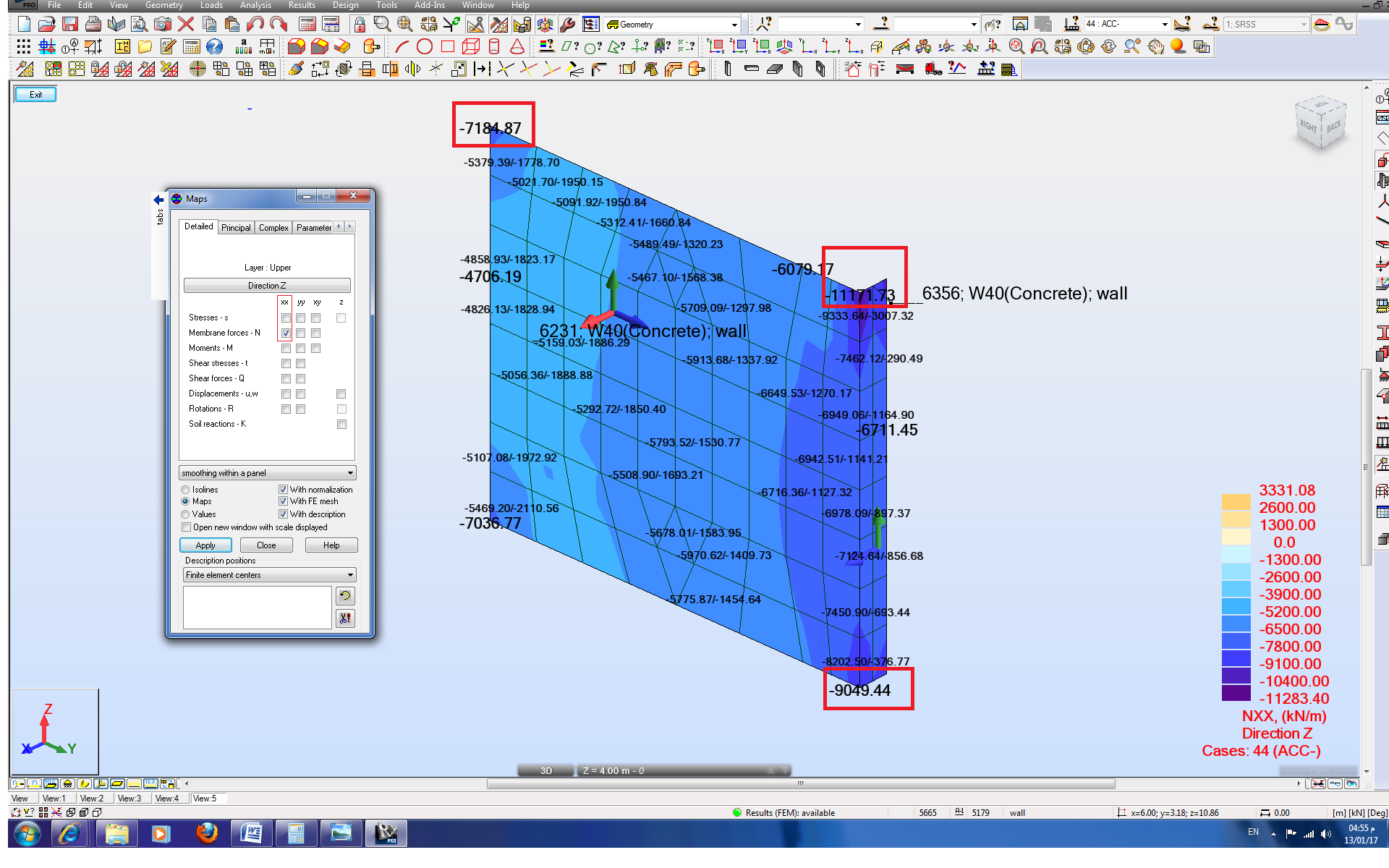
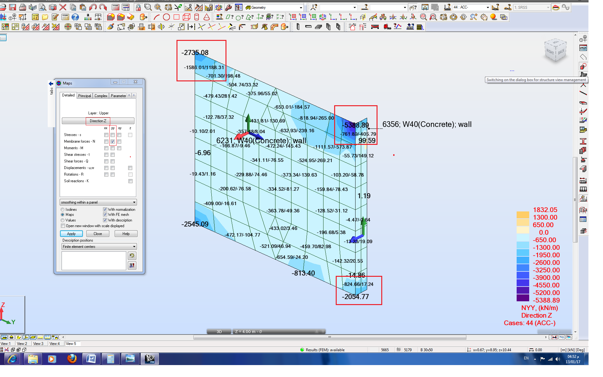
Please , take a look to the attached capture which shows high values(Nxx& Nyy ) at the nodes where ROBOT can't calculate the required reinforcement compared with the other elements.
What is your comment about these results ?
Note : if you use any capture for explanation . Kindly , send it as attached.
Thanks for your cooperation
Refaat
Message 10 of 14
01-18-2013
03:19 AM
- Mark as New
- Bookmark
- Subscribe
- Mute
- Subscribe to RSS Feed
- Permalink
- Report
01-18-2013
03:19 AM
I think that the results in tee corners are influenced by the fact that this is very 'rigid' part due to sizes of the beams. Actually it seems that you may say that in reality there is no wall in these locations but beams instead.
If you find your post answered press the Accept as Solution button please. This will help other users to find solutions much faster. Thank you.
Artur Kosakowski
Message 11 of 14
01-21-2013
02:03 AM
- Mark as New
- Bookmark
- Subscribe
- Mute
- Subscribe to RSS Feed
- Permalink
- Report
01-21-2013
02:03 AM
Dear Artur
-I apologize to repeat my inquire again since the same message appears even in the simple models as you can see in the attached captures. They represent simple shear wall exposed to only horizontal force. Also, these nodes (ROBOT can't generate the reinforcement) doesn't represent the max. area of steel.
- What can I use for reinforcement for the elements because as you see in the capture , there is a big difference between the edge and the center for the same element? in other word can I use the value which is at the center ?
Thanks for your cooperation
Refaat
Message 12 of 14
01-21-2013
05:48 AM
- Mark as New
- Bookmark
- Subscribe
- Mute
- Subscribe to RSS Feed
- Permalink
- Report
01-21-2013
05:48 AM
Display the map of forces that you you want to use for reinforcement calculations and check if they are similar in the node and in the center of the element. You can also try to use denser mesh in these areas and see if the 'range' of the problem is 'reduced' to even smaller part around this node. Mind that the areas at the location of the concentrated force are more likely to have some inaccuracy of results due to the mathematical functions that define the surface elements.
If you find your post answered press the Accept as Solution button please. This will help other users to find solutions much faster. Thank you.
Artur Kosakowski
Message 13 of 14
01-22-2013
02:31 AM
- Mark as New
- Bookmark
- Subscribe
- Mute
- Subscribe to RSS Feed
- Permalink
- Report
01-22-2013
02:31 AM
Dear Artur
I will be too much thankful if you give me radical solution without (Estimate the results from the neighboring elements instead ) or using (denser mesh).
Best Regards
Refaat
Message 14 of 14
01-23-2013
08:25 AM
- Mark as New
- Bookmark
- Subscribe
- Mute
- Subscribe to RSS Feed
- Permalink
- Report
01-23-2013
08:25 AM
Refaat,
If you expect that I know a hidden button to press so that it displays the value in the node where Robot is currently not able to calculate it then I'm sorry but I don't. ![]()
On the other hand there are some things that I can do (and which I do when looking at issues reported on the forum):
- I can try to propose a workable solution when I'm able to find it. In this particular case that is the averaging of values from the neighboring points where the reinforcement is calculated. You can see these points marked in green on the attached picture.
- I can try to find out and explain why something happened. As I mentioned to determine the area of required reinforcement Robot uses the iterative approach. The initial calculations of reinforcement for the set of forces from the 'red' node are such that there is no need for reinforcement but during the verification of the solution the capacity (with no reinforcement) is calculated as 0.98 (should be >= 1) which results in lack of the convergence of the process and lack of results in this node. This indicates that the minimal reinforcement provisions will be just fine there. Why this happens is to be determined by the development team.
- I can document and register all issues that require further investigation by the development team or should be treated as development requests for the next versions of Robot.
If you find your post answered press the Accept as Solution button please. This will help other users to find solutions much faster. Thank you.
Artur Kosakowski
Reply
Topic Options
- Subscribe to RSS Feed
- Mark Topic as New
- Mark Topic as Read
- Float this Topic for Current User
- Bookmark
- Subscribe
- Printer Friendly Page
Forums Links
Can't find what you're looking for? Ask the community or share your knowledge.
Post to forums
