Community
- Forums Home
- >
- Robot Structural Analysis Products Community
- >
- Robot Structural Analysis Forum
- >
- Re: Uniform planar load on contour
Robot Structural Analysis Forum
Welcome to Autodesk’s Robot Structural Analysis Forums. Share your knowledge, ask questions, and explore popular Robot Structural Analysis topics.
Turn on suggestions
Auto-suggest helps you quickly narrow down your search results by suggesting possible matches as you type.
Reply
Topic Options
- Subscribe to RSS Feed
- Mark Topic as New
- Mark Topic as Read
- Float this Topic for Current User
- Bookmark
- Subscribe
- Printer Friendly Page
Message 1 of 22
Anonymous
4989 Views, 21 Replies
05-19-2011
10:25 AM
- Mark as New
- Bookmark
- Subscribe
- Mute
- Subscribe to RSS Feed
- Permalink
- Report
05-19-2011
10:25 AM
Uniform planar load on contour
Hi to everyone....
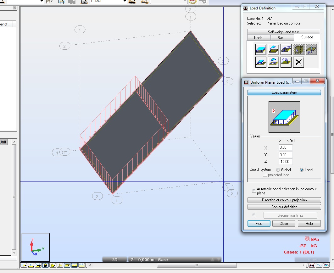
...I'm trying to apply a planar load on a cladding's local Z direction using the „Uniform planar load on contour“ command. Unfortunately the software makes no difference between global and local coordinate system, basically the direction of the applied load is always according the global Z axis....See the attached screenshot!
Is there a real software problem or am I doing something wrong?
Any comments would be highly appreciated!
Regards!
21 REPLIES 21
Message 2 of 22
05-19-2011
12:06 PM
- Mark as New
- Bookmark
- Subscribe
- Mute
- Subscribe to RSS Feed
- Permalink
- Report
05-19-2011
12:06 PM
Yes, it is a bug if you choose (as you did) uniform or 3P load on CONTOUR. If the load applies to the whole panel ,then it works perfectly. So ,the workaround is (if you really need to apply the load on only a part of the area) dividing the area on 2 or more panels and use only the planar load applied to the whole panel. Rafael
Rafael Medeiros
Did you find this post helpful? Feel free to Like this post.
Did your question get successfully answered? Then click on the ACCEPT SOLUTION button.
Message 3 of 22
Anonymous
in reply to:
Anonymous
05-19-2011
11:19 PM
- Mark as New
- Bookmark
- Subscribe
- Mute
- Subscribe to RSS Feed
- Permalink
- Report
05-19-2011
11:19 PM
Thank you! That's what I did,......hope someone of the RSA stuff will notice this thread and fix the bug!
Regards!
Message 4 of 22
05-19-2011
11:30 PM
- Mark as New
- Bookmark
- Subscribe
- Mute
- Subscribe to RSS Feed
- Permalink
- Report
05-19-2011
11:30 PM
The load should be applied correctly and there is no need to divide a panel into parts. Mind that for such load type you should use another type of load display as shown on the attached picture. Make sure that you run model generation or calculate the file before displaying the loads. To check if the load is correctly applied verify the sum of the reactions – you should have horizontal reactions in addition to the vertical ones. I hope this clarifies this issue.
Regards,
Artur Kosakowski
Message 5 of 22
05-20-2011
06:44 AM
- Mark as New
- Bookmark
- Subscribe
- Mute
- Subscribe to RSS Feed
- Permalink
- Report
05-20-2011
06:44 AM
thx Artur. It would be great if the load could be displayed right without having to generate the model.Anyway ,the Help content from uniform load on contour already says exactly what you explained here. It´s great that now, in this official autodesk forum ,we can have a proper support!! thx again
Rafael Medeiros
Did you find this post helpful? Feel free to Like this post.
Did your question get successfully answered? Then click on the ACCEPT SOLUTION button.
Message 6 of 22
05-20-2011
07:03 AM
- Mark as New
- Bookmark
- Subscribe
- Mute
- Subscribe to RSS Feed
- Permalink
- Report
05-20-2011
07:03 AM
@Rafacascudo wrote:
It would be great if the load could be displayed right without having to generate the model.
Due to the nature of this load this is not possible. At the stage you define the load the direction of the local Z axes of a panel is 'not known' yet. Only during the model generation this is 'checked' and the 'correct' direction of the load is determined. I think that we can agree that performing such check each time you define this kind of load may not be the functionality you would like to see especially for larger models, however I agree that this would be nice.
Regards,
Artur Kosakowski
Message 7 of 22
05-20-2011
08:49 AM
- Mark as New
- Bookmark
- Subscribe
- Mute
- Subscribe to RSS Feed
- Permalink
- Report
05-20-2011
08:49 AM
This " 'not known' yet " ,what does it mean? , cause as soon as you create a panel, the local axes are available and are displayed if you want to ,without generating the model.Couldn´t the load also be " correctly" displayed according to this " premature" local system?
Rafael Medeiros
Did you find this post helpful? Feel free to Like this post.
Did your question get successfully answered? Then click on the ACCEPT SOLUTION button.
Message 8 of 22
05-20-2011
09:15 AM
- Mark as New
- Bookmark
- Subscribe
- Mute
- Subscribe to RSS Feed
- Permalink
- Report
05-20-2011
09:15 AM
@Rafacascudo wrote:
This " 'not known' yet " ,what does it mean? , cause as soon as you create a panel, the local axes are available and are displayed if you want to ,without generating the model.Couldn´t the load also be " correctly" displayed according to this " premature" local system?
This is not that simple. To display the load correctly the analysis of the panel geometry and detection of surface elements to which the load should be applied is required. This is what I refer to as the model generation. If you look at the attached picture you can see that the direction of the panel is a 'simplified' term which in fact should be replaced by the detection of local directions of each of surface elements being 'within' the load contour and this should be done for number of panels rather then a single one as the load contour can be defined 'outside' the model and projected in various directions.
Artur Kosakowski
Message 9 of 22
05-22-2011
11:49 PM
- Mark as New
- Bookmark
- Subscribe
- Mute
- Subscribe to RSS Feed
- Permalink
- Report
Message 10 of 22
05-25-2011
02:36 PM
- Mark as New
- Bookmark
- Subscribe
- Mute
- Subscribe to RSS Feed
- Permalink
- Report
05-25-2011
02:36 PM
Hi Dear users of ARSA,
I am doing actually analysis on an existing continuous bridge truss, the challenge is consisting by replaced the existing deck by a new one wich will be post-tensioned. Doing it with ARSA would be grateful, by taking account of the possibility to models the built-up section of the different members by ourselves, and by the using of the inelegance line tool, but if we want to taking account of the lateral variation of the truck load, for the different lanes (4 in my case), we have to create 3 mobile axes in each lane load. The notion of lane load is prescribe by the AAHASTO LARD, and the CHBDC SO-06 even by the new EUROCODE.
Unfortunately the bridge Autoloader was discontinuous for the resents versions of Robot without any explanation of the technical team of ARSA, in my case I have to do the modeling in SAP 14.02 which taking account of the design and analysis parameters for multiple lanes in bridge structures.
If anyone could help me about this topic that will be grateful.
See the doc in attachment that I have sent to the Robot Staff since more than one year without receiving any answer.
Message 11 of 22
09-28-2016
06:40 AM
- Mark as New
- Bookmark
- Subscribe
- Mute
- Subscribe to RSS Feed
- Permalink
- Report
09-28-2016
06:40 AM
Hi. A bout this two problems with planar loads on contour. I made the follow test: - 3 same structures - on the left: two uniform planar loads on contour, in local coordinate system: wrong picture, wrong result - in the middle: one uniform planar load, in local coordinate system: right picture, right result - on the right: one planar loads (3 points), in local coordinate system: wrong picture, right result Five years later the begining of this topic, does Autodesk find a real solution to this big and "basic" problem according to a design software???
Message 12 of 22
09-28-2016
07:43 AM
- Mark as New
- Bookmark
- Subscribe
- Mute
- Subscribe to RSS Feed
- Permalink
- Report
Message 13 of 22
09-28-2016
08:04 AM
- Mark as New
- Bookmark
- Subscribe
- Mute
- Subscribe to RSS Feed
- Permalink
- Report
Message 14 of 22
09-28-2016
08:08 AM
- Mark as New
- Bookmark
- Subscribe
- Mute
- Subscribe to RSS Feed
- Permalink
- Report
09-28-2016
08:08 AM
Sorry, I can't add attachment. I can send you the file mail if you want?
Message 15 of 22
09-28-2016
08:17 AM
- Mark as New
- Bookmark
- Subscribe
- Mute
- Subscribe to RSS Feed
- Permalink
- Report
09-28-2016
08:17 AM
You shouldn't have any issue with this - try to zip the files. Alternatively please check:
http://forums.autodesk.com/t5/robot-structural-analysis-forum/sending-bigger-files/td-p/3795062
Artur Kosakowski
Message 16 of 22
09-28-2016
08:26 AM
- Mark as New
- Bookmark
- Subscribe
- Mute
- Subscribe to RSS Feed
- Permalink
- Report
Message 17 of 22
09-30-2016
04:24 AM
- Mark as New
- Bookmark
- Subscribe
- Mute
- Subscribe to RSS Feed
- Permalink
- Report
09-30-2016
04:24 AM
@Anonymous wrote:
Hi. A bout this two problems with planar loads on contour. I made the follow test: - 3 same structures - on the left: two uniform planar loads on contour, in local coordinate system: wrong picture, wrong result - in the middle: one uniform planar load, in local coordinate system: right picture, right result - on the right: one planar loads (3 points), in local coordinate system: wrong picture, right result Five years later the begining of this topic, does Autodesk find a real solution to this big and "basic" problem according to a design software???
"wrong picture"
The display of a defined load may not be intuitive however it is as designed and don on purpose. The contour limiting the area of the load can be defined not only in a plane of a panel but as separated from the model whereas the load can be applied to many panels at the same time (imagine a 30 story building so you can define this load one time rather than 30 times). To add additional flavor the surfaces you apply this loads to can be of entirely different orientation and the diction of load projection can be in the arbitrary direction too. This makes this load type very versatile but backfires when you actually want to see the load on the objects you applied them to the moment you have defined it as its exact 'form' is unknown at this stage yet. As the final loads can look differently for each of the object they are applied to they are shown as automatically generated loads after running the model generation.
"on the left: two uniform planar loads on contour, in local coordinate system: wrong result"
The bars the load is 'assigned' to are discretized with certain accuracy and the length of each of the contour does't match exactly with this discretization. The result is that the tributary area length assigned to each bars is slightly longer than the halves of their lengths. This results in the value of the actual load being slightly smaller than for two other models and as these loads overlap in the middle of the panel the bending moments are slightly higher whereas the reactions are the same.. This can be avoided when you e.g. define a node at the middle of a bar.
If you find your post answered press the Accept as Solution button please. This will help other users to find solutions much faster. Thank you.
Artur Kosakowski
Message 18 of 22
10-06-2016
01:42 AM
- Mark as New
- Bookmark
- Subscribe
- Mute
- Subscribe to RSS Feed
- Permalink
- Report
10-06-2016
01:42 AM
Your answer looks to be very complicated. I undurstand that there is no simple solution to this problem. The designer needs to look the load at the screen to be sure it is correcly applied on the plan, as every other loads, and it is really a problem to verify wind effects. That is what we ask to a design software.
Message 19 of 22
09-17-2023
03:36 PM
- Mark as New
- Bookmark
- Subscribe
- Mute
- Subscribe to RSS Feed
- Permalink
- Report
09-17-2023
03:36 PM
Unfortunately, I am not able to see the load, perpendicular to the plan after running the FEA. Is there something I am doing wrong?
Is there a way to display the original load perpendicular to the cladding (10kN/m2)?

Reply
Topic Options
- Subscribe to RSS Feed
- Mark Topic as New
- Mark Topic as Read
- Float this Topic for Current User
- Bookmark
- Subscribe
- Printer Friendly Page
Forums Links
Can't find what you're looking for? Ask the community or share your knowledge.
Post to forums
