Community
- Forums Home
- >
- Robot Structural Analysis Products Community
- >
- Robot Structural Analysis Forum
- >
- Re: Transformation of Panels to Solids
Robot Structural Analysis Forum
Welcome to Autodesk’s Robot Structural Analysis Forums. Share your knowledge, ask questions, and explore popular Robot Structural Analysis topics.
Turn on suggestions
Auto-suggest helps you quickly narrow down your search results by suggesting possible matches as you type.
Transformation of Panels to Solids
10 REPLIES 10
SOLVED
Reply
Topic Options
- Subscribe to RSS Feed
- Mark Topic as New
- Mark Topic as Read
- Float this Topic for Current User
- Bookmark
- Subscribe
- Printer Friendly Page
Message 1 of 11
Anonymous
2093 Views, 10 Replies
07-04-2012
11:33 PM
- Mark as New
- Bookmark
- Subscribe
- Mute
- Subscribe to RSS Feed
- Permalink
- Report
07-04-2012
11:33 PM
Hello,
I have been working on a 3-D channel which has a varying cross-section. I modelled it using the "panel" property and then tried to convert it to a "solid" section. However, I was not able to do that.(See "Panel Model") It gives an error ("The solid has not been created").
Afterwards, I tried to model a single cross-section with the "panel" property and then extruded it, however the channel has varying cross-sections and my model was wrong. (See "Extrude Model")
Can you please propose a solution to my problem?
Thanks in advance
Solved! Go to Solution.
Solved by Rafal.Gaweda. Go to Solution.
10 REPLIES 10
Message 2 of 11
07-05-2012
01:02 AM
- Mark as New
- Bookmark
- Subscribe
- Mute
- Subscribe to RSS Feed
- Permalink
- Report
07-05-2012
01:02 AM
It should work : movie: http://screencast.com/t/3CXaPazGs749
Check whether all panels are flat and connected or send us file.
Rafal Gaweda
Message 3 of 11
02-12-2013
12:57 PM
- Mark as New
- Bookmark
- Subscribe
- Mute
- Subscribe to RSS Feed
- Permalink
- Report
Message 4 of 11
02-13-2013
12:29 AM
- Mark as New
- Bookmark
- Subscribe
- Mute
- Subscribe to RSS Feed
- Permalink
- Report
02-13-2013
12:29 AM
In case of steel bars you can import model to ASD Steel.
The if you want you can export it as ACIS *.sat file.
Rafal Gaweda
Message 5 of 11
03-05-2014
05:09 AM
- Mark as New
- Bookmark
- Subscribe
- Mute
- Subscribe to RSS Feed
- Permalink
- Report
03-05-2014
05:09 AM
Hi,
I have difficulties in creating a 3D solid out of a panel element which consists of number of sides. When I click create solid from list of objects and pick my panel it seems to create a volumetric object, i.e. it appears in the list but it is not visible and when I delete the panel element there is nothing left on the screen.
I have imported the 3D geometry from ACIS file.
Can you please help. I have attached the .rtd file.
Regards,
Adrian
Message 6 of 11
03-05-2014
05:50 AM
- Mark as New
- Bookmark
- Subscribe
- Mute
- Subscribe to RSS Feed
- Permalink
- Report
03-05-2014
05:50 AM
It is necessary to highlight the object, right mouse click to open the context menu and select Object Properties.
Then in the Object Properties it is necessary to change the object type from Shell to Solid:

But why you model such a thin-walled tube as solid?
Sufficient precision of solid elements will require at least 2 finite elements along the thickness of the wall - it will result in some abnormal number of elements.
Regards,
Pawel Pulak
Technical Account Specialist
Message 7 of 11
03-05-2014
06:19 AM
- Mark as New
- Bookmark
- Subscribe
- Mute
- Subscribe to RSS Feed
- Permalink
- Report
03-05-2014
06:19 AM
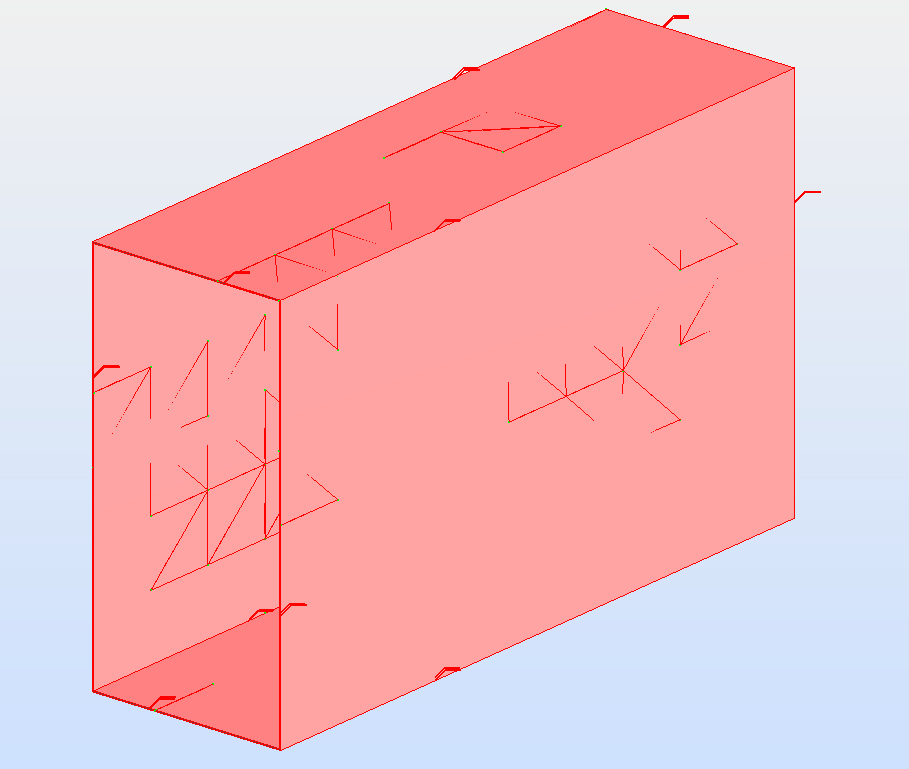
Thanks for that Pawel,
I have figured now how to convert it but encountered problems when meshing it. It just doesn't create a complete mesh on the solid (see attached).
Is there a way of transforming initial geometry i.e. panel consisting of sides into a tube (i.e. shell but with single surface)?
The problem is that this is just an extract from the whole, very complex model that was imported from .sat file. The imported model consists of 'panels' (consisting of sides) but they have a separate internal and external face of every wall and I'm looking for an automatic way of transforming 3D solids into analytical model (either shell or solid). As you say shell would be more appropriate but would probably require manually deleting either external or internal face of the duct (tube) which is impractical.
Kind regards,
Adrian
Message 8 of 11
03-05-2014
07:25 AM
- Mark as New
- Bookmark
- Subscribe
- Mute
- Subscribe to RSS Feed
- Permalink
- Report
03-05-2014
07:25 AM
Some possibilities to obtain shell model of the rectangular tube in case of model as yours - panels corresponding to all faces (inner, outer and front faces of walls) of the solid):
1/ or selecting inner and front faces of walls and setting them as Inactive using Geometry > Objects > Inactive Sides, then meshing the outer faces
2/ or meshing all faces, freezing meshes, then deleting meshes from the inner and front faces leaving only the outer ones
3/ or defining the contour corresponding to the front face of the tube, selecting it and extruding along the length of the tube, deleting the original model, meshing the extruded panel. As in the video available using this link:
http://screencast.com/t/fK87si3p2
Needless to say that my choice would be 3/ 🙂
In cases 1/ or 2/ necesary to select to base the tube on the outer or inner surface of walls. Irregular mesh on ACIS objects.
In case 3/ possible to define the contour corresponding to the center of walls, regular rectangular mesh of extruded panels
Regards,
Pawel Pulak
Technical Account Specialist
Message 9 of 11
03-05-2014
09:14 AM
- Mark as New
- Bookmark
- Subscribe
- Mute
- Subscribe to RSS Feed
- Permalink
- Report
03-05-2014
09:14 AM
Pawel,
Thanks for your advice which is very appropriate for small models. The problem is, that my geometry is a bit more complicated (hundreds of segments of various geometry, not necessarilly as straight forward as the example.
Any idea how I could deal with the whole model (maybe using Autocad?, Revit?)
Kind regards,
Adrian
Message 10 of 11
03-06-2014
09:13 AM
- Mark as New
- Bookmark
- Subscribe
- Mute
- Subscribe to RSS Feed
- Permalink
- Report
03-06-2014
09:13 AM
Yes, in case of very irregular models the approaches proposed by me may be inefficient.
The best would be some tool converting solids to mid-surface shells - but it does not exist in AutoCAD or Revit.
If all your solids are so thin-walled as the attached example then using inner or outer surface will not result in significant inaccuracy.
In such case you can try to import solids to AutoCAD, here EXPLODE them to regions, delete unnecessary regions leaving only those corresponding to outer or inner surfaces, then export it to SAT file.
This SAT file can be opened in Robot and regions will be read as faces (objects), which can be selected to create panels.
It is only one of possible workflows - probably not the best one. May be others will have better ideas...
Regards,
Pawel Pulak
Technical Account Specialist
Message 11 of 11
03-07-2014
12:38 AM
- Mark as New
- Bookmark
- Subscribe
- Mute
- Subscribe to RSS Feed
- Permalink
- Report
03-07-2014
12:38 AM
As concerns some tool converting solids to mid-surface shells it is available for instance in Autodesk Inventor.
See this post:
Regards,
Pawel Pulak
Technical Account Specialist
Reply
Topic Options
- Subscribe to RSS Feed
- Mark Topic as New
- Mark Topic as Read
- Float this Topic for Current User
- Bookmark
- Subscribe
- Printer Friendly Page
Forums Links
Can't find what you're looking for? Ask the community or share your knowledge.
Post to forums
