Community
- Forums Home
- >
- Robot Structural Analysis Products Community
- >
- Robot Structural Analysis Forum
- >
- Re: Timber Tapered Beam
Robot Structural Analysis Forum
Welcome to Autodesk’s Robot Structural Analysis Forums. Share your knowledge, ask questions, and explore popular Robot Structural Analysis topics.
Turn on suggestions
Auto-suggest helps you quickly narrow down your search results by suggesting possible matches as you type.
Reply
Topic Options
- Subscribe to RSS Feed
- Mark Topic as New
- Mark Topic as Read
- Float this Topic for Current User
- Bookmark
- Subscribe
- Printer Friendly Page
Message 1 of 9
06-29-2012
02:10 AM
- Mark as New
- Bookmark
- Subscribe
- Mute
- Subscribe to RSS Feed
- Permalink
- Report
06-29-2012
02:10 AM
Hi,
I can’t understand the results of the calculation on a timber tapered beam.
In the attached example, the cross section is a rectangular beam 26x45cm. The additional checks are enabled, yet the section in which the verification is done is the one at minimal height (at the beginning of the beam: W=8775,00 cm3), but with the maximum bending moment (Md=359,60kNm).
Why is that?
Solved! Go to Solution.
Solved by Artur.Kosakowski. Go to Solution.
8 REPLIES 8
Message 2 of 9
06-29-2012
02:45 AM
- Mark as New
- Bookmark
- Subscribe
- Mute
- Subscribe to RSS Feed
- Permalink
- Report
Message 3 of 9
07-02-2012
03:27 AM
- Mark as New
- Bookmark
- Subscribe
- Mute
- Subscribe to RSS Feed
- Permalink
- Report
07-02-2012
03:27 AM
These additional parameters are intended for switching on additional verifications that are requested for the profile types shown on the pictures. They do not change the section you defined in the model (so the basic checks are done for in your case for the cross section with the constant height) but result in additional checks being done (see the attached picture).
In your example you should define the beam as two tapered bars with the 'tapered' timber design label assigned.
If you find your post answered press the Accept as Solution button please. This will help other users to find solutions much faster. Thank you.
Artur Kosakowski
Message 4 of 9
07-02-2012
08:15 AM
- Mark as New
- Bookmark
- Subscribe
- Mute
- Subscribe to RSS Feed
- Permalink
- Report
07-02-2012
08:15 AM
Artur, thanks for your answer.
But I do not still understand why the Sig_m,d in the example is 44,59MPa
I Think that is from this calculation: Sig_m,d=kl * Md / W = 1,09 * 359,690 / 8,775 = 44,7MPa very close at the result 44,59MPa.
But in the formula 6.41 of EC5, W is calculated in the apex zone; thus W must be calculated with the max height (0,72m) and the result of the calculation is Sig_m,d=kl * Md / W = 1,09 * 359,690 / 22,464 = 17,45MPa very far from 44,7MPa.
In the same way I think that the calculation of Sig_t,90,d is overestimated: it is the calculation of the tensile stress perpendicular to grain and this tensile stress must be only in the max height zone (0,72m).
I kindly ask you to send me your opinion about this matter.
Best regards
Angelo
Message 5 of 9
07-03-2012
12:06 AM
- Mark as New
- Bookmark
- Subscribe
- Mute
- Subscribe to RSS Feed
- Permalink
- Report
07-03-2012
12:06 AM
Angelo,
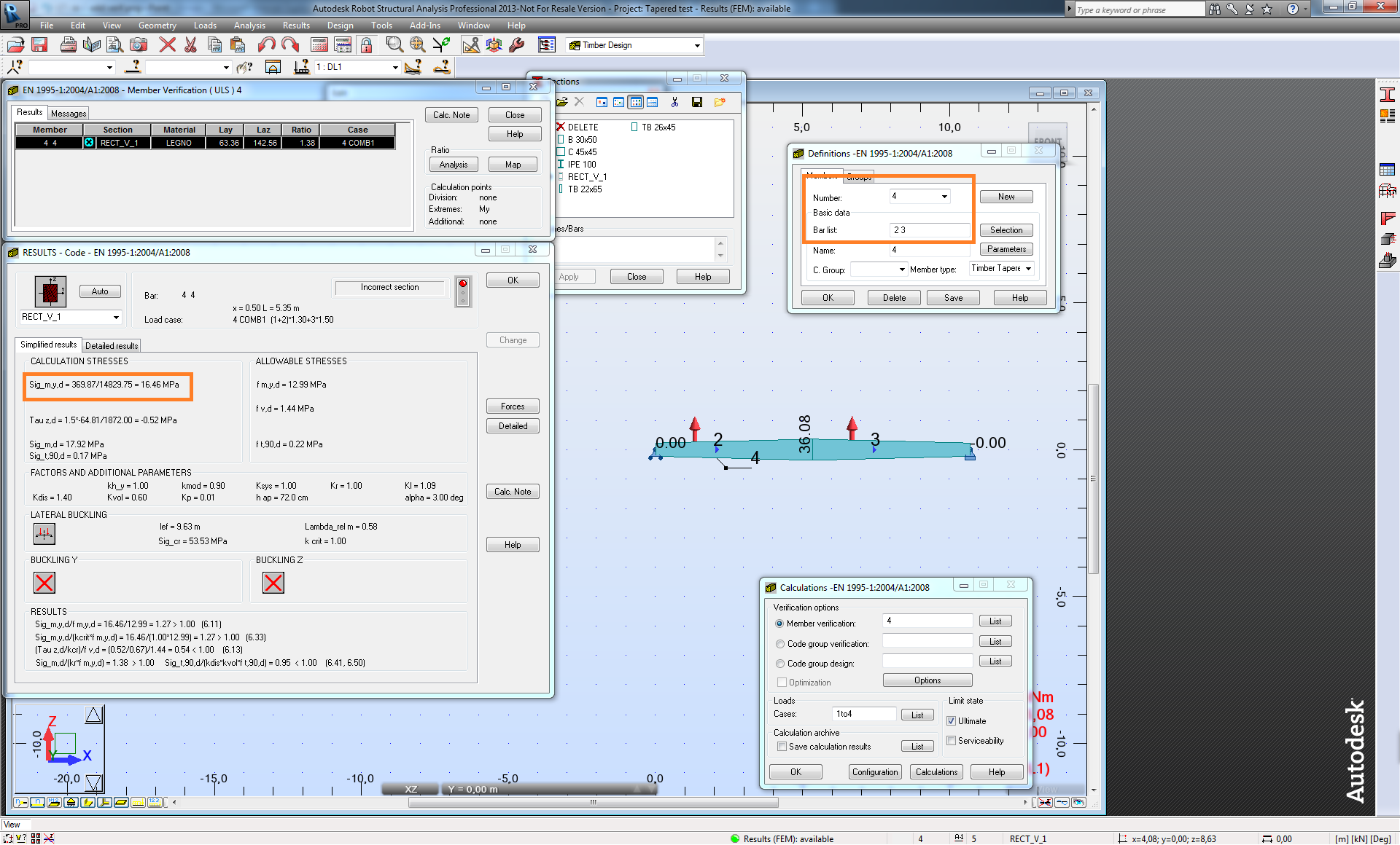
As I wrote in my previous answer the selection of a beam shape you make in the EC5 parameters assigned to a bar does not change its cross section from uniform height to the tapered one. Its aim is to switch on additional verifications that are not needed for a section with the constant height. If you look at the picture I attached previously you can see that the correct approach is to model the tapered beam in the structure (member 4 created from bars 2 and 3) and then run its verification with additional tapered beam verification switched on. If you look at the verification dialog I attached you can see that the value of stresses in the middle of the beam (marked with the orange rectangle)is calculated for the height in this location rather than the value at the beginning of the beam.
If you find your post answered press the Accept as Solution button please. This will help other users to find solutions much faster. Thank you.
Artur Kosakowski
Message 6 of 9
03-20-2017
10:04 AM
- Mark as New
- Bookmark
- Subscribe
- Mute
- Subscribe to RSS Feed
- Permalink
- Report
03-20-2017
10:04 AM
Please clarify how to turn on additional verification - I can't find the dialog box shown in your screenshot.
Message 7 of 9
03-21-2017
01:37 AM
- Mark as New
- Bookmark
- Subscribe
- Mute
- Subscribe to RSS Feed
- Permalink
- Report
03-21-2017
01:37 AM
Here you are:

If you find your post answered press the Accept as Solution button please. This will help other users to find solutions much faster. Thank you.
Artur Kosakowski
Message 8 of 9
03-21-2017
03:49 AM
- Mark as New
- Bookmark
- Subscribe
- Mute
- Subscribe to RSS Feed
- Permalink
- Report
03-21-2017
03:49 AM
Thanks. Does this apply only to timber beams or is there an equivalent for steel beams?
Message 9 of 9
03-21-2017
03:58 AM
- Mark as New
- Bookmark
- Subscribe
- Mute
- Subscribe to RSS Feed
- Permalink
- Report
03-21-2017
03:58 AM
Applies to timber design only.
If you find your post answered press the Accept as Solution button please. This will help other users to find solutions much faster. Thank you.
Artur Kosakowski
Reply
Topic Options
- Subscribe to RSS Feed
- Mark Topic as New
- Mark Topic as Read
- Float this Topic for Current User
- Bookmark
- Subscribe
- Printer Friendly Page
