Community
- Forums Home
- >
- Robot Structural Analysis Products Community
- >
- Robot Structural Analysis Forum
- >
- Re: sizing slab
Robot Structural Analysis Forum
Welcome to Autodesk’s Robot Structural Analysis Forums. Share your knowledge, ask questions, and explore popular Robot Structural Analysis topics.
Turn on suggestions
Auto-suggest helps you quickly narrow down your search results by suggesting possible matches as you type.
Reply
Topic Options
- Subscribe to RSS Feed
- Mark Topic as New
- Mark Topic as Read
- Float this Topic for Current User
- Bookmark
- Subscribe
- Printer Friendly Page
Message 1 of 8
01-04-2012
04:33 AM
- Mark as New
- Bookmark
- Subscribe
- Mute
- Subscribe to RSS Feed
- Permalink
- Report
01-04-2012
04:33 AM
Hi Arthur
I am new at using Robot, and need some assistense to take the next step.
I am in the prosess of sizing a slab. Calculations seems to complete succesfully, but when I alter det thickness I get the same deflection values.
Could you please take a quick look at my file and guide me in the right direction (see attached file)
Your efforts are much appriciated:-)
Solved! Go to Solution.
Solved by Artur.Kosakowski. Go to Solution.
7 REPLIES 7
Message 2 of 8
01-04-2012
05:22 AM
- Mark as New
- Bookmark
- Subscribe
- Mute
- Subscribe to RSS Feed
- Permalink
- Report
01-04-2012
05:22 AM
Could you make screen captures that illustrate the values you obtained as well as the corresponding load case number and thickness applied to the panel in both cases please?
Artur Kosakowski
Message 3 of 8
01-04-2012
05:55 AM
- Mark as New
- Bookmark
- Subscribe
- Mute
- Subscribe to RSS Feed
- Permalink
- Report
01-04-2012
05:55 AM
The required reinforcement differs for the two slabs whereas I get lower values over support for the 250mm slab, and less in midspan at bottom etc.
Attached are screenshoots
Thanks again
Message 4 of 8
01-04-2012
06:29 AM
- Mark as New
- Bookmark
- Subscribe
- Mute
- Subscribe to RSS Feed
- Permalink
- Report
01-04-2012
06:29 AM
In both cases the required reinforcement is at the minimal required area and the difference is caused by area of steel vs. area of concrete ratio limit (more steel for the thicker slab) with the exception of the locations over the columns. If you display the stiffness reduction factor for both slab you can see that it is approx. 1.77 and 1.74 respectively which means that the value of displacements in both cases for the equivalent stiffness method are expected to be similar.
You can see the difference after running the deflection verification with the stiffness update (I'm attaching the pictures showing this difference for case 21).
If you find your post answered press the Accept as Solution button please. This will help other users to find solutions much faster. Thank you.
Artur Kosakowski
Message 5 of 8
01-04-2012
08:12 AM
- Mark as New
- Bookmark
- Subscribe
- Mute
- Subscribe to RSS Feed
- Permalink
- Report
01-04-2012
08:12 AM
thanks for the quick response.
Even though the stiffness reduction factor are approx the same for the 250mm and the 300mm, Young's Modulus for slab 300mm is relatively higher than the slab 250mm which should result in different deflections.
In addition, I am expecting larger deflections for a slab spanning 7m in both directions carrying a live load of 2.5kN/m2 + selfweight.
I have probable done something wrong but cant seem to figure out what.
If you have any further suggestions to what I can do diffently or if I have forgotten something, it would be much appriciated.
Message 6 of 8
01-05-2012
01:05 AM
- Mark as New
- Bookmark
- Subscribe
- Mute
- Subscribe to RSS Feed
- Permalink
- Report
01-05-2012
01:05 AM
Even though the stiffness reduction factor are approx the same for the 250mm and the 300mm, Young's Modulus for slab 300mm is relatively higher than the slab 250mm which should result in different deflections.
This is correct (stiffness rather than E itself
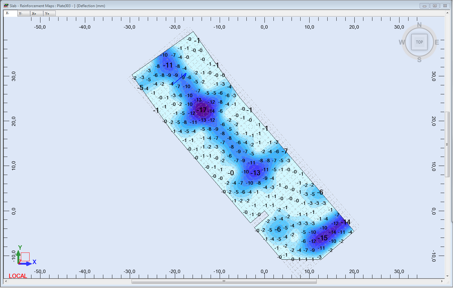
) and you can see the difference in values of displacements of nodes for SLS type combinations (see attached pictures) which are 6mm (250 mm) and 4 mm (300 mm) calculated at the static analysis stage but you have to take into account that the equivalent stiffness method used for cracked deflection of a panel is the simplified approach and may not be accurate as it averages the stiffness from the whole panel. If you want to use this method for accuracy of the results you may consider modeling the floor as number of panels limited by the support conditions (e.g. number of rectangular panels with corners at the columns) as shown on the next picture I'm attaching. The stiffness update method 'changes' stiffness of each of the element of the mesh based on calculated area of reinforcement and crack width and then the model is calculated again which results in much more accurate value of cracked deflection of the panel (for this method the number of panels that represent the floor is irrelevant). As you can see on the pictures I attached to my previous answer the difference between cracked deflection can be clearly seen (11 mm vs. 7 mm).
In addition, I am expecting larger deflections for a slab spanning 7m in both directions carrying a live load of 2.5kN/m2 + selfweight.
I'm not able to estimate the deflection of the continuous multi span slab that works in both directions but looking at the values of crack which are basically 0s with the exception of the parts above the columns (slab reinforcement being at the minimal level) the ratio between cracked and uncracked (static analysis) seems reasonable to me.
250 mm: stiffness update: 11/6 = 1.8
300 mm: stiffness update: 7/4 = 1.8
I have probable done something wrong but cant seem to figure out what.
If you have any further suggestions to what I can do diffently or if I have forgotten something, it would be much appriciated.
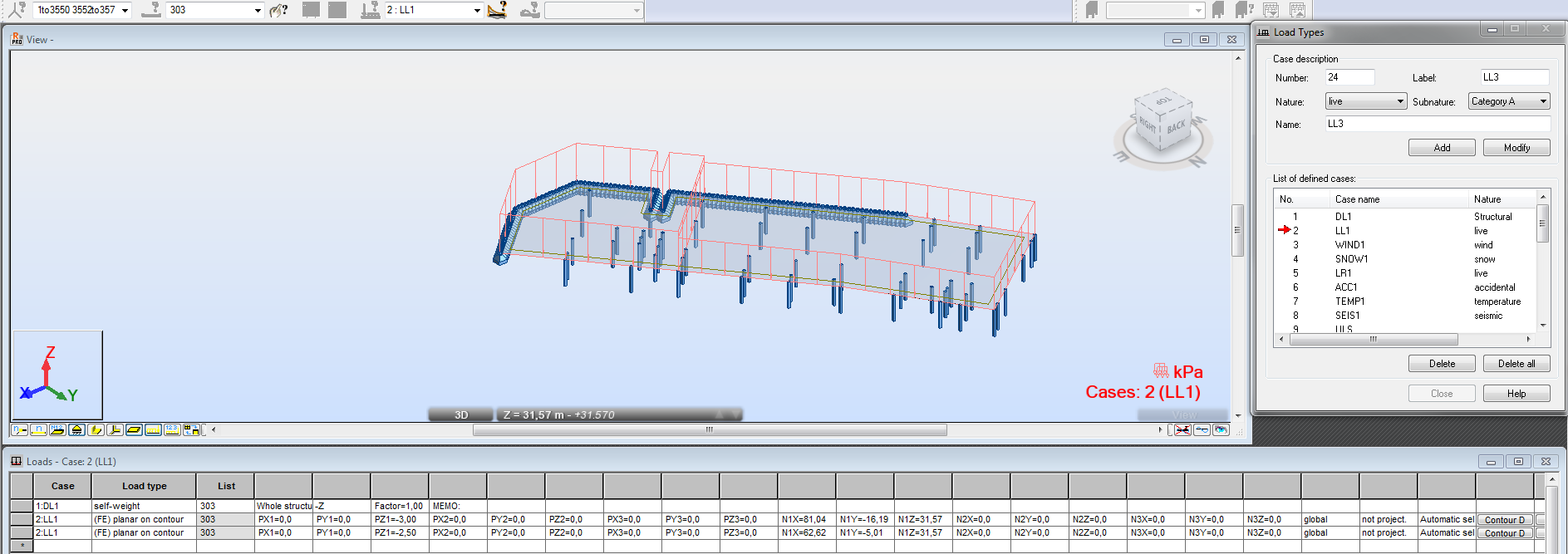
Perhaps you should redefine the live loads. If they are defined within a single load case they are applied to the whole panel (area on which they are defined) rather than divided into sub loads that are applied in the areas limited by 4 columns and combined within themselves. In other words with such definition of the live the deflection will be smaller (to illustrate: multi span beam with load applied on all spans vs. each second span) then if there are several live load cases with loads applied on smaller parts of the panel (similar approach to modeling the floor with number of smaller panels) with appropriate combinations defined.
Artur Kosakowski
Message 7 of 8
01-05-2012
06:02 AM
- Mark as New
- Bookmark
- Subscribe
- Mute
- Subscribe to RSS Feed
- Permalink
- Report
01-05-2012
06:02 AM
Hi Arthur
That helped alot, thank you.
However, I get an error I don't know have to fix.
When I run the calculation for required reinfocement, I get an error telling the following:
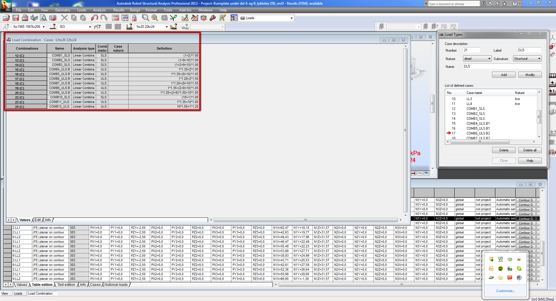
* Required types are not ascribed to SLS combinations
* The admissible cracking value has been exceeded for panel no. 303
How do I fix these errors? Ref attachments
Does the 'automatic combination' find the worst combination of loads, or should you do this manually?
When performing verification, how do I choose the worst combination of SLS without manually checking all of them?
Message 8 of 8
01-05-2012
06:30 AM
- Mark as New
- Bookmark
- Subscribe
- Mute
- Subscribe to RSS Feed
- Permalink
- Report
01-05-2012
06:30 AM
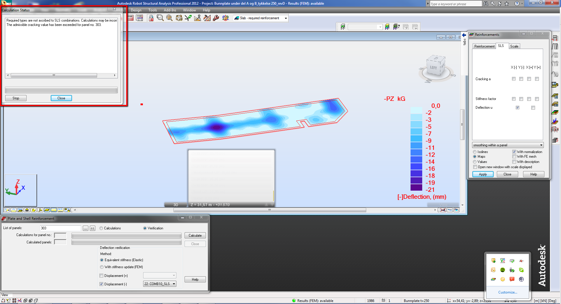
However, I get an error I don't know have to fix.
When I run the calculation for required reinfocement, I get an error telling the following:
* Required types are not ascribed to SLS combinations
* The admissible cracking value has been exceeded for panel no. 303
How do I fix these errors? Ref attachments
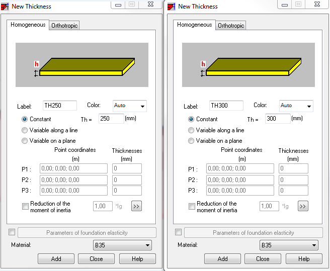
Please make sure that creating combinations you assigned the appropriate type as required by the RC design code you selected (see the attached picture).
Does the 'automatic combination' find the worst combination of loads, or should you do this manually?
This tool automatically creates number of combinations based on the regulation file you selected in Job Preferences. During the design you are supposed to provide the list of combinations you want to include in this process and the program uses them one by one e.g. for calculating necessary area of reinforcement due to bending etc.
When performing verification, how do I choose the worst combination of SLS without manually checking all of them?
I would check the values of displacements obtained for calculations of the model (static analysis) and identify these combinations that produce the largest values. Then I would run verification of the deflection with the stiffness update for them.
If you find your post answered press the Accept as Solution button please. This will help other users to find solutions much faster. Thank you.
Artur Kosakowski
Reply
Topic Options
- Subscribe to RSS Feed
- Mark Topic as New
- Mark Topic as Read
- Float this Topic for Current User
- Bookmark
- Subscribe
- Printer Friendly Page
