Community
- Forums Home
- >
- Robot Structural Analysis Products Community
- >
- Robot Structural Analysis Forum
- >
- RC BEAMS - Moments differences between results and RC Design
Robot Structural Analysis Forum
Welcome to Autodesk’s Robot Structural Analysis Forums. Share your knowledge, ask questions, and explore popular Robot Structural Analysis topics.
Turn on suggestions
Auto-suggest helps you quickly narrow down your search results by suggesting possible matches as you type.
RC BEAMS - Moments differences between results and RC Design
3 REPLIES 3
SOLVED
Reply
Topic Options
- Subscribe to RSS Feed
- Mark Topic as New
- Mark Topic as Read
- Float this Topic for Current User
- Bookmark
- Subscribe
- Printer Friendly Page
Message 1 of 4
11-25-2012
08:35 PM
- Mark as New
- Bookmark
- Subscribe
- Mute
- Subscribe to RSS Feed
- Permalink
- Report
11-25-2012
08:35 PM
Hi all
1.- My question is how to interpret the following difference between the
The moments from the static analysis results and those for which the beam should be design
please take a look to the attached file
The complete file is in
https://www.dropbox.com/sh/t791xb9yd91idch/Dy4f96cn6u
2.- How to run in order to optimize this structure
in the RC module the reinforcement parameters for optimizing are "open"or without boundaries
however it takes the given section dimensions and fails
For your time and advice thanks in advance
Marcelo
Solved! Go to Solution.
Solved by Artur.Kosakowski. Go to Solution.
3 REPLIES 3
Message 2 of 4
11-26-2012
02:39 AM
- Mark as New
- Bookmark
- Subscribe
- Mute
- Subscribe to RSS Feed
- Permalink
- Report
11-26-2012
02:39 AM
1.- My question is how to interpret the following difference between the
The moments from the static analysis results and those for which the beam should be design
please take a look to the attached file
I'm not sure if I understand this point correctly. Looking at the parts indicated in green i think that the results are the same: M_after_redistribution at 4.700m = 699.31 and at x=4.711 is is 682.62.
2.- How to run in order to optimize this structure
in the RC module the reinforcement parameters for optimizing are "open"or without boundaries
however it takes the given section dimensions and fails
As far as I can see you have the problem with torsion as it is difficult to manage correct reinforcement distribution for very short spans and cantilevers generated due to the way you modelled and imported the beam 123. I would suggest modelling and designing the beam in the way shown on the attached picture instead.
If you find your post answered press the Accept as Solution button please. This will help other users to find solutions much faster. Thank you.
Artur Kosakowski
Message 3 of 4
11-26-2012
03:53 AM
- Mark as New
- Bookmark
- Subscribe
- Mute
- Subscribe to RSS Feed
- Permalink
- Report
11-26-2012
03:53 AM
Thanks Artur
for the quick response
The point is
in green it seems to be ok the small dif. is only the mouse pointer to be at 4.7m
The other values for the other spans
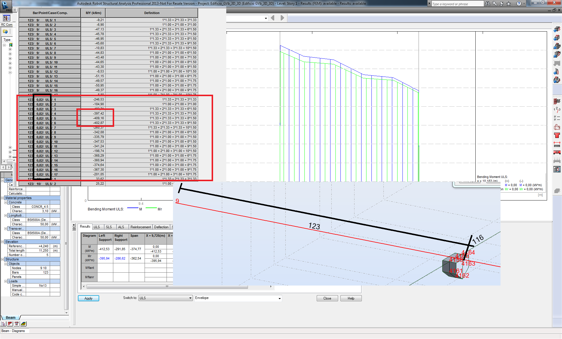
in the second picture you can find this legend
Highlighted in blue
For P3 My max = 974.92 953.87 kNm
(where 953.87 is from the beam note and 974.92 is from the Results layout)
For P4
My max = -533.21 -395.94 kNm
(where -395.94 is from the beam note and -533.21 is from the Results layout)
Message 4 of 4
11-26-2012
05:02 AM
- Mark as New
- Bookmark
- Subscribe
- Mute
- Subscribe to RSS Feed
- Permalink
- Report
11-26-2012
05:02 AM
Highlighted in blue
For P3 My max = 974.92
953.87kNm(where 953.87 is from the beam note and 974.92 is from the Results layout)
The accuracy of the import depends on number of points you decide on. In addition I would consider modeling the beam with no vertical offset which influences bending.
For P4
My max = -533.21
-395.94kNm(where -395.94 is from the beam note and -533.21 is from the Results layout)
Values are from the support faces.
Please see: http://forums.autodesk.com/t5/Autodesk-Robot-Structural/RC-BEAMS-Design-of-structure-beam-at-the-col...
Artur Kosakowski
Reply
Topic Options
- Subscribe to RSS Feed
- Mark Topic as New
- Mark Topic as Read
- Float this Topic for Current User
- Bookmark
- Subscribe
- Printer Friendly Page
