Community
- Forums Home
- >
- Robot Structural Analysis Products Community
- >
- Robot Structural Analysis Forum
- >
- Re: Load distribution from purlins to beams
Robot Structural Analysis Forum
Welcome to Autodesk’s Robot Structural Analysis Forums. Share your knowledge, ask questions, and explore popular Robot Structural Analysis topics.
Turn on suggestions
Auto-suggest helps you quickly narrow down your search results by suggesting possible matches as you type.
Load distribution from purlins to beams
3 REPLIES 3
Reply
Topic Options
- Subscribe to RSS Feed
- Mark Topic as New
- Mark Topic as Read
- Float this Topic for Current User
- Bookmark
- Subscribe
- Printer Friendly Page
Message 1 of 4
07-02-2012
02:23 AM
- Mark as New
- Bookmark
- Subscribe
- Mute
- Subscribe to RSS Feed
- Permalink
- Report
07-02-2012
02:23 AM
Load distribution from purlins to beams
Hi there,
I cannot understand how the distribution of loads is taking place from purlins to beams.
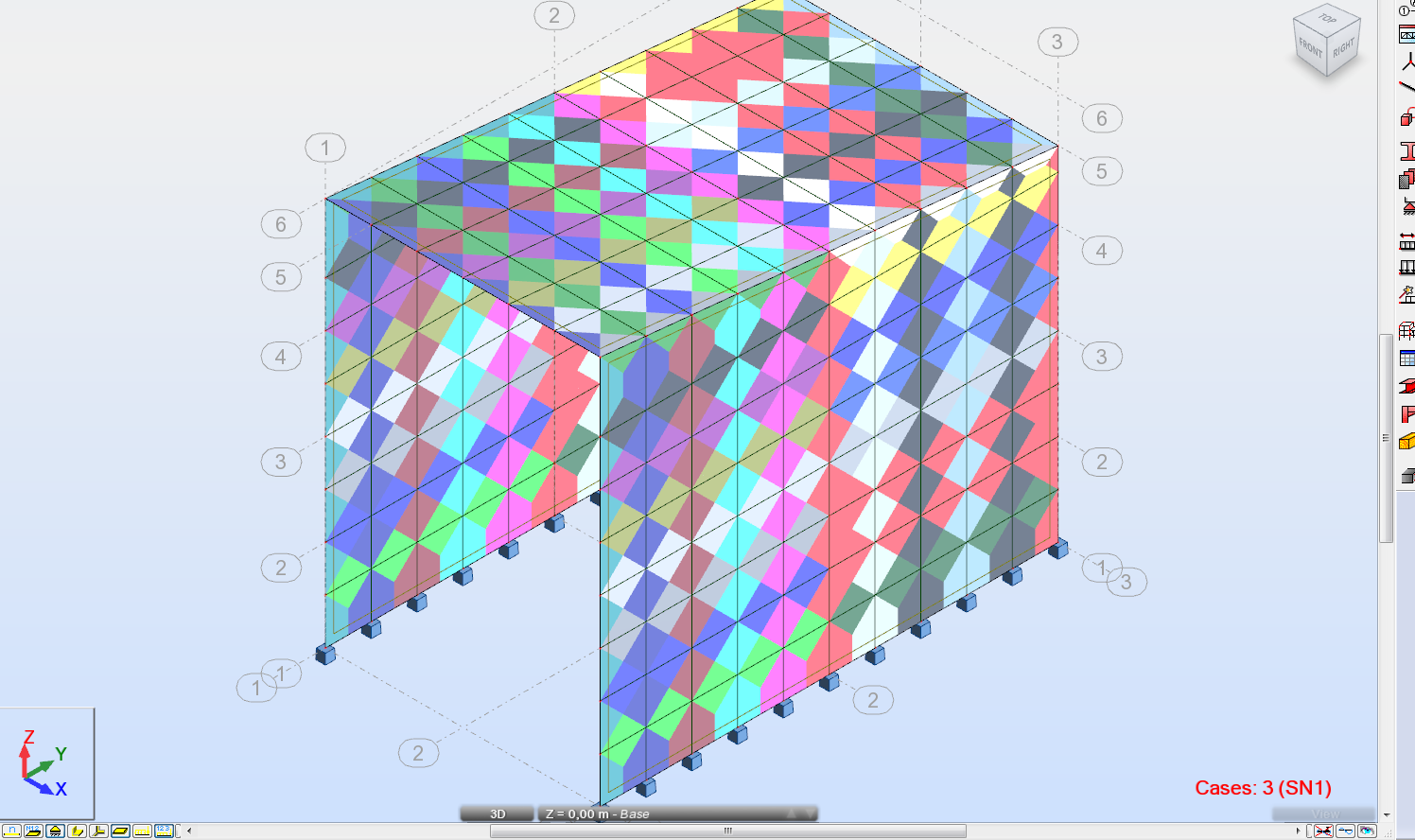
In the attached picture I have surface loads on claddings that are distributed fine on the purlins (eg 44,45,42,43 etc). But, because I have drawn the purlins half the lenght of the building, the loads are distributed only to the beams that the purlins are stepping on. For example purlin 44 tranfers load only to 5 and 11 beams.
Is there a way to distibute loads to all beams through the purlins lenght without having to break the purling in every juction?
If I offset the purlins will I be able to use releases as the purlins are pinned at both ends?
Thanks a lot.
3 REPLIES 3
Message 2 of 4
07-02-2012
02:45 AM
- Mark as New
- Bookmark
- Subscribe
- Mute
- Subscribe to RSS Feed
- Permalink
- Report
07-02-2012
02:45 AM
Check the settings of your cladding ; Oneway or two? Correct Direction ?
Check display of forces generated automatically.

Rafal Gaweda
Message 3 of 4
07-02-2012
03:11 AM
- Mark as New
- Bookmark
- Subscribe
- Mute
- Subscribe to RSS Feed
- Permalink
- Report
07-02-2012
03:11 AM
I had one-way x direction of load distribution, Meaning that the cladding load will be distributed on the purlins and then from the purlins to the beam as concentrated loads to the points where the purlin is stepping on the beam.
If I use two-way direction distribution the loads are distibuted trapezodially on both purlins and beams something that is not correct.
See attachments. If you look closely the distributed load at beam 11)middle one) and on the beams at the edges is uniform rectangular but on the the rest is trapezodial....
Message 4 of 4
07-02-2012
04:32 AM
- Mark as New
- Bookmark
- Subscribe
- Mute
- Subscribe to RSS Feed
- Permalink
- Report
07-02-2012
04:32 AM
See attachments. If you look closely the distributed load at beam 11)middle one) and on the beams at the edges is uniform rectangular but on the the rest is trapezodial....
Divide these beams (5 11 32 34) by nodes situated on them
Rafal Gaweda
Reply
Topic Options
- Subscribe to RSS Feed
- Mark Topic as New
- Mark Topic as Read
- Float this Topic for Current User
- Bookmark
- Subscribe
- Printer Friendly Page
