Community
- Forums Home
- >
- Robot Structural Analysis Products Community
- >
- Robot Structural Analysis Forum
- >
- Re: Cable sag due to Thermal
Robot Structural Analysis Forum
Welcome to Autodesk’s Robot Structural Analysis Forums. Share your knowledge, ask questions, and explore popular Robot Structural Analysis topics.
Turn on suggestions
Auto-suggest helps you quickly narrow down your search results by suggesting possible matches as you type.
Reply
Topic Options
- Subscribe to RSS Feed
- Mark Topic as New
- Mark Topic as Read
- Float this Topic for Current User
- Bookmark
- Subscribe
- Printer Friendly Page
Message 1 of 5
10-22-2013
01:28 PM
- Mark as New
- Bookmark
- Subscribe
- Mute
- Subscribe to RSS Feed
- Permalink
- Report
10-22-2013
01:28 PM
I want to determine the amount of sag in the cables due to an increase in temperature. However I have attempted by both the thermal load case and also moving my end node based on the change in length due to a 90 degree temperature change. Intuitively members 1 and 2 should have some vertical deflection due to this induced sag.
Ultimately I want to determine my reaction at node 3 to verify its positive or negative with some initial pretension.
Right now the model shows no deflection values or reactions along any of the intermediate attachments.
Anyone able to help me determine what i'm doing wrong?
Thanks in advance.
Solved! Go to Solution.
Solved by Pawel.Pulak. Go to Solution.
4 REPLIES 4
Message 2 of 5
10-23-2013
12:58 AM
- Mark as New
- Bookmark
- Subscribe
- Mute
- Subscribe to RSS Feed
- Permalink
- Report
10-23-2013
12:58 AM
First some questions related to your model:
1/ I assume that the direction of gravity in your model is -Y. Is it true?
2/ Do you want to apply an increase or decrease in temperature? Because in load case 4 I have noticed TX=-90 It corresponds to the decrease of 90 degrees Fahrenheit.
3/ What are the starting conditions of the cable? What is the tension force in it before applying temperature load or what is the original (unloaded) length of the cable?
In your model you have not defined any element loads (including self-weight) applied to cables in the assembling load case (case number 1). In such situation cables are calculated by Robot as tension-only truss bars - because there are no loads which can results in sag and cable-like behavior.
Regards,
Pawel Pulak
Technical Account Specialist
Message 3 of 5
10-23-2013
05:07 AM
- Mark as New
- Bookmark
- Subscribe
- Mute
- Subscribe to RSS Feed
- Permalink
- Report
10-23-2013
05:07 AM
Pawel, thanks for the response.
1) Gravity is in the y-direction
2) Ideally i want to analyze model with both increase and decrease in temperature. Typically i'm more concerned with a decrease however for my inquiry the load case should read +90 to create a sag in the model.
3)There is a 69 lb pretension force in the cable during assembly. The original length of the cable is as shown from the nodes.
The self weight of the cable i have put in as a nodal force at the top node to "hang" the entire mesh from the top. I enter this weight in as an "additional" load not assembly.
Thanks.
Message 4 of 5
10-23-2013
07:53 AM
- Mark as New
- Bookmark
- Subscribe
- Mute
- Subscribe to RSS Feed
- Permalink
- Report
10-23-2013
07:53 AM
I have modified your model according to your explanations.
Some of modifications made:
1/ selfweight in -Y defined in the assembling load case (case 1)
2/ unnecessary load in load case 2 replaced the the thermal increase load of +90 degrees
3/ load cases 1 2 and 4 renamed to better describe loads applied in them
4/ I have not changed loads in other load cases because I am not sure whet are they modeling
5/ I have deleted combinations because of modifications made in case 2 and my explanations given below these points - please re-define them considering these remarks
6/ unified parameters of nonlinear analysis in all load cases
Such model is attached to this message.
As already mentioned in some other posts of this forum in Robot in case of structures containing cables the assembling load case is automatically added to all consecutive load cases and combinations.
As concerns combinations, even if the assembling load case is not directly specified in the definition of combinations it is considered in them with the factor of 1.0 (Robot takes care of not cumulating it from various cases composing combinations). If the assembling load case is directly specified in the definition of combination with some factor then this factor "overwrites" the default factor of 1.0.
Above behavior can be checked and verified in the table of reactions looking at values of the sums of forces and reactions for various load cases at the bottom of this table.
In addition to the modified model I have also attached some screen captures made for load cases 1(selfweight), 2 (Thermal increase) and 3 (Thermal decrease).
It can be noticed that the tension force in the cable in the assembling load case 1 (selfweight) is changing from 87.1 lb on the top to 68.2 lb on the bottom. In the definition of the bottom segment of the cable you have specified a 69 lb pretension force. It is measured along the cord in the middle of this segment so youu can se that it corresponds to 69.8 lb at the top of it and 68.2 lb at the bottom. The change of FX along the cable is caused by selfweight load applied to it and sag.
The best way to estimate sag in cable structures is to display exact deformation and to activate "Deformation in structure scale". In such case the factor of 1 corresponds to deformation "in scale" with the structure. In this screen capture the factor of 50 (the deformation exaggerated 50 times) is used to see any visible sag.
In load case 2 the temperature is increased by 90 degreees - it results in significant decrease of tension forces in the cable (between 20.6 lb at the top and 1.7 lb at the bottom) and significant increase of the sag (in this case the factor of 2 is enough to see any visible sag).
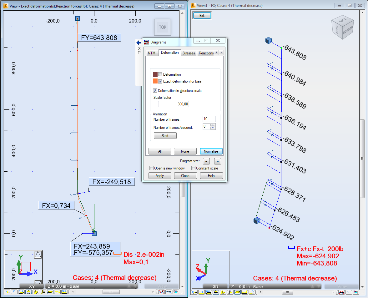
In load case 4 the temperature is decreased by 90 degreees - it results in significant increase of tension forces in the cable (between 643.8 lb at the top and 624.9 lb at the bottom) and significant decrease of the sag (in this case the factor of 300 is necessary to see any visible sag).
I hope these explanations will be helpful.
Regards,
Pawel Pulak
Technical Account Specialist
Message 5 of 5
10-23-2013
07:55 AM
- Mark as New
- Bookmark
- Subscribe
- Mute
- Subscribe to RSS Feed
- Permalink
- Report
10-23-2013
07:55 AM
...and the screen capture for Thermal decrease
Regards,
Pawel Pulak
Technical Account Specialist
Reply
Topic Options
- Subscribe to RSS Feed
- Mark Topic as New
- Mark Topic as Read
- Float this Topic for Current User
- Bookmark
- Subscribe
- Printer Friendly Page
