Community
- Forums Home
- >
- Robot Structural Analysis Products Community
- >
- Robot Structural Analysis Forum
- >
- Bug? in AISC 360-05 steel design (Shear calc appears wrong)
Robot Structural Analysis Forum
Welcome to Autodesk’s Robot Structural Analysis Forums. Share your knowledge, ask questions, and explore popular Robot Structural Analysis topics.
Turn on suggestions
Auto-suggest helps you quickly narrow down your search results by suggesting possible matches as you type.
Bug? in AISC 360-05 steel design (Shear calc appears wrong)
3 REPLIES 3
SOLVED
Reply
Topic Options
- Subscribe to RSS Feed
- Mark Topic as New
- Mark Topic as Read
- Float this Topic for Current User
- Bookmark
- Subscribe
- Printer Friendly Page
Message 1 of 4
11-01-2012
10:13 PM
- Mark as New
- Bookmark
- Subscribe
- Mute
- Subscribe to RSS Feed
- Permalink
- Report
11-01-2012
10:13 PM
First off, I'm usually wrong on this and the bug was user error on my end. That said, I can't find my error. It's probably obvious at first glance but I'm stuck and need to get some work done.
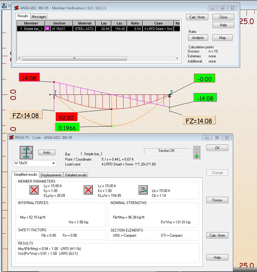
The beam is a standard W16x31 A572-50.
Loading is:
1. Uniform dead load of 200 lbs / ft
2. Uniform snow load of 1000 lbs / ft
Beam is unbraced except at the supports.
I have LRFD load combinations as well as ASD load combinations setup. Beam design was done with LRFD.
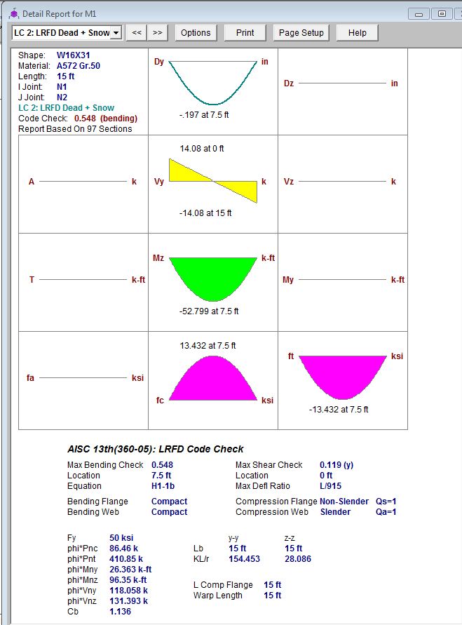
The problem is that the shear reported is off by a substantial amount. It should be 14.8 kips for the LRFD Dead + Snow load combination (1.2 x Dead + 1.6 x Snow). The moment is correct at 52.8 Kip*ft.
I have attached the Robot file, and screen shots of both Robot and a Risa check calc.
Solved! Go to Solution.
Solved by Artur.Kosakowski. Go to Solution.
3 REPLIES 3
Message 2 of 4
11-05-2012
01:36 AM
- Mark as New
- Bookmark
- Subscribe
- Mute
- Subscribe to RSS Feed
- Permalink
- Report
11-05-2012
01:36 AM
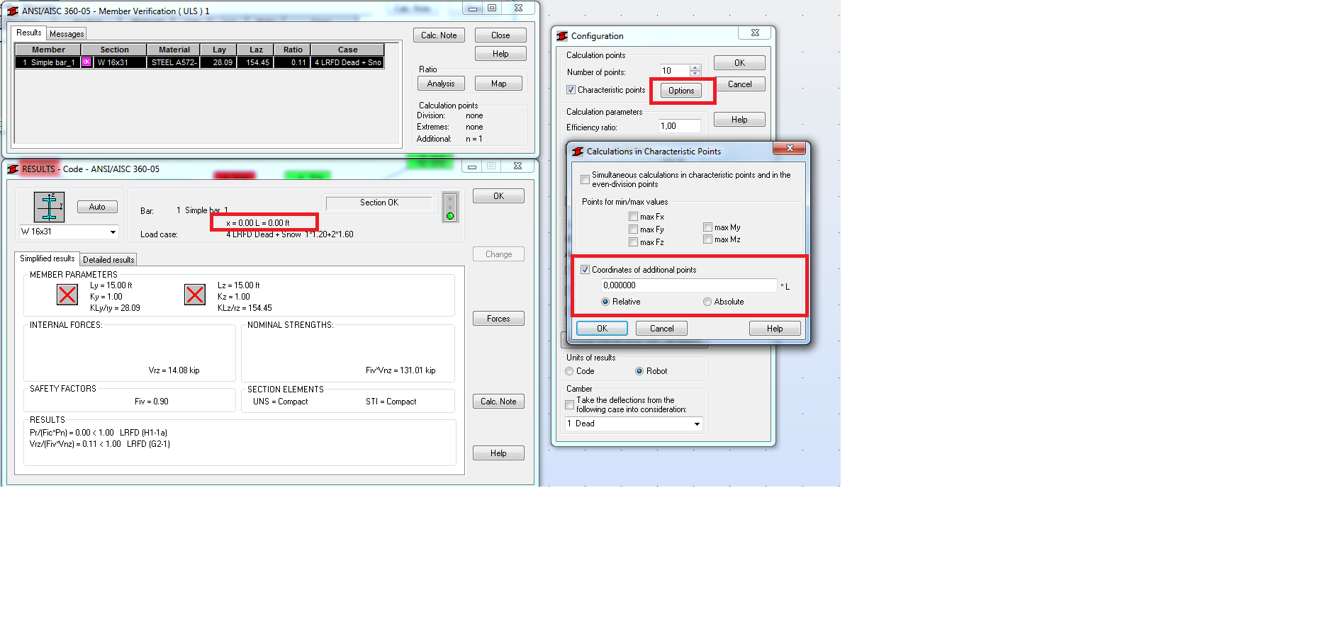
If you look at the RISA results you will see that the verification for shear is done at the beginning of the beam rather than in the location of the max. bending. To compare results you should set the verification point at x=0L in Robot.
If you find your post answered press the Accept as Solution button please. This will help other users to find solutions much faster. Thank you.
Artur Kosakowski
Message 3 of 4
11-05-2012
01:53 PM
- Mark as New
- Bookmark
- Subscribe
- Mute
- Subscribe to RSS Feed
- Permalink
- Report
11-05-2012
01:53 PM
I was confused because the design shear listed is not the worst case design shear for the whole beam. I assume that Robot is infact checking for the worst case shear, but it doesn't occur where the max moment happened, which goverened the design.
Just to make sure I understand this correctly:
1. Robot is checking the worst case shear, but only the internal forces from the worst case location are listed. Both max shear and max moment would not be listed in the internal forces section as they would occure in different locations.
2. I don't have to explicity tell Robot to check the shear at 0ft and 15ft in order to make sure that the worst case shear is accounted for in the design. The only reason to do this is to see the actual worst case loads at a particular point. Is this correct?
3. Robot is only printing the results for one location on the beam that generated the largest unity equation check. In other words, while the worst case shear unity check (Vrz / Fiv*Vnz = 0.113) is greater than the 0.01 shown in the calc, it wasn't shown because the moment check was 0.54.
Message 4 of 4
11-06-2012
12:36 AM
- Mark as New
- Bookmark
- Subscribe
- Mute
- Subscribe to RSS Feed
- Permalink
- Report
11-06-2012
12:36 AM
1. Robot is checking the worst case shear, but only the internal forces from the worst case location are listed. Both max shear and max moment would not be listed in the internal forces section as they would occure in different locations.
Correct.
2. I don't have to explicity tell Robot to check the shear at 0ft and 15ft in order to make sure that the worst case shear is accounted for in the design. The only reason to do this is to see the actual worst case loads at a particular point. Is this correct?
The verification is done in number of points you decided on in the configuration dialog. By default this is done in the 3 points (beginning - middle - end) of each calculation element.
3. Robot is only printing the results for one location on the beam that generated the largest unity equation check. In other words, while the worst case shear unity check (Vrz / Fiv*Vnz = 0.113) is greater than the 0.01 shown in the calc, it wasn't shown because the moment check was 0.54.
Correct.
Artur Kosakowski
Reply
Topic Options
- Subscribe to RSS Feed
- Mark Topic as New
- Mark Topic as Read
- Float this Topic for Current User
- Bookmark
- Subscribe
- Printer Friendly Page
