Community
Revit MEP Forum
Welcome to Autodesk’s Revit MEP Forums. Share your knowledge, ask questions, and explore popular Revit MEP topics.
Turn on suggestions
Auto-suggest helps you quickly narrow down your search results by suggesting possible matches as you type.
Reply
Topic Options
- Subscribe to RSS Feed
- Mark Topic as New
- Mark Topic as Read
- Float this Topic for Current User
- Bookmark
- Subscribe
- Printer Friendly Page
Message 1 of 14
08-06-2008
12:18 PM
- Mark as New
- Bookmark
- Subscribe
- Mute
- Subscribe to RSS Feed
- Permalink
- Report
08-06-2008
12:18 PM
Multi Circuit Wire Tick Marks
When you have a multi circuit home run Revit will properly add home run arrows and phase/hot wires. However it will not add additional neutral or ground wires. If you have more than 3 circuits (usually A/B/C phase) in a home run it is necessary to run an additional neutral. Additionally if you have less than 3 circuits and more than one are on the same phase (ie. ckt 1 and 2 are both on phase A) they must have their own neutral. Revit does not accommodate this.
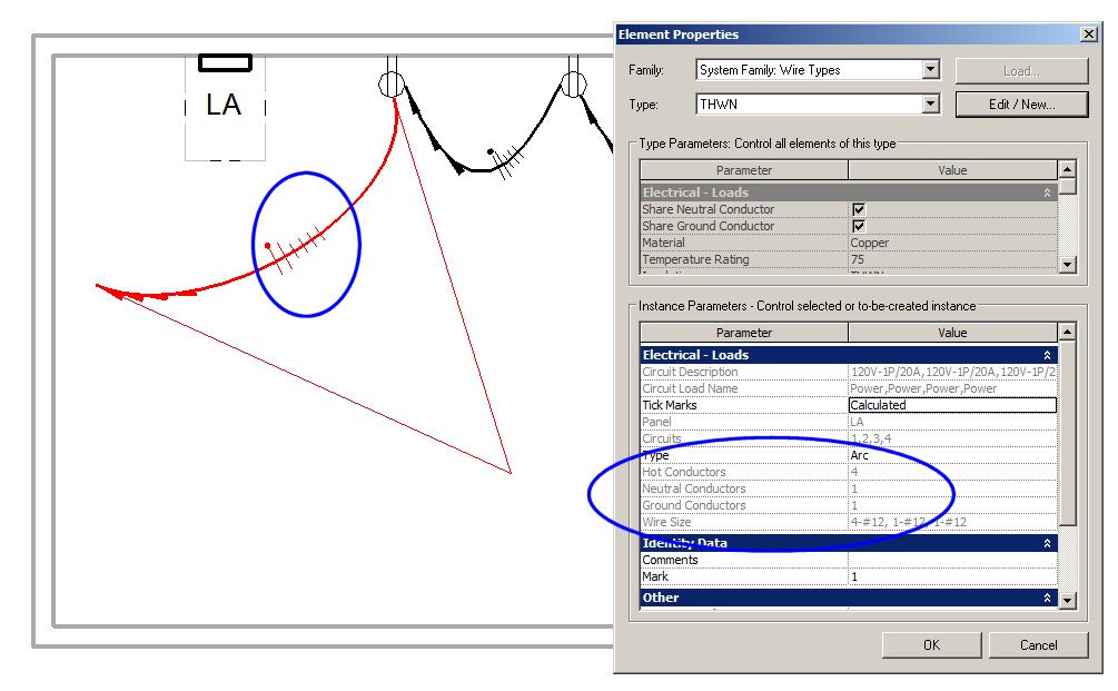
To compound matters, if the home run is a multi circuit then you cannot manually modify the number of wire ticks (see attached jpg). On a single circuit home run I can modify the number of wire ticks for each wire (hot, neutral, and ground), but as soon as I make it a multi circuit home run this is disabled.
What is the purpose of the Tick Marks=Calculated/On/Off property? I can tell when the property is off the tick is not displayed, but Calculated/On do not seem to have any effect.
I also tried creating a new wire type that had the "Share Neutral Conductor" and "Share Ground Conductor" unchecked. This seemed to have no effect, so I am not sure what these Family Parameters govern.
Is there something I am missing or is this a Revit limitation/oversight?
thanks,
Jeff
13 REPLIES 13
Message 2 of 14
01-02-2013
09:08 AM
- Mark as New
- Bookmark
- Subscribe
- Mute
- Subscribe to RSS Feed
- Permalink
- Report
01-02-2013
09:08 AM
TexasJetter,
Were you ever given any response to this? I just had this question come up, and I don't see that it is any different in 2012 MEP. What did you end up doing?
Thanks,
Casey
Message 3 of 14
01-25-2013
03:15 PM
- Mark as New
- Bookmark
- Subscribe
- Mute
- Subscribe to RSS Feed
- Permalink
- Report
01-25-2013
03:15 PM
I am also dealing with a similar issue with the tick marks. I am working in Revit MEP 2013 and there still doesn't seem to be a way for Revit to produce the desired result on its own. I believe this is an instance where I am just going to have to "fake" the information. In my case I have used a j-box family with multiple connectors for the multiple loads so that it shows up correctly on my panel schedules. I will have to manually draw the home run and to represent the number of nutrals and hots in the order that I want and then creat a group out if those elements. It will be a visual represnetation only and I will have to use a standard piece of annotation to describe the home run information. I don't know of any other way to show the tick marks for multiple circuits such as these. I would be interested to know what others have done to work around this issue.
Message 4 of 14
06-06-2013
11:01 AM
- Mark as New
- Bookmark
- Subscribe
- Mute
- Subscribe to RSS Feed
- Permalink
- Report
06-06-2013
11:01 AM
For you people who are seeing these issues with lack of content development for Revit, do the benefits of Revit pay off? I work for a company with about 10 people in the CAD department, and only 1 knows Revit enough to work in it, but he only does 3D coordination and detail work ... not basic electrical wiring.
The lack of wiring is one reason we, as a company, have not moved to Revit. Do you people see a benefit to the automatic scheduling that outweigh the loss of wire customization and other "lack of electrical development"-related issues?
I'm curious to know,
Shawn
Shawn B.
 ||
|| 

To help improve Autodesk Products, please Click Here to Vote for ideas and submit your own.
To help improve Autodesk Products, please Click Here to Vote for ideas and submit your own.
Message 5 of 14
06-06-2013
03:37 PM
- Mark as New
- Bookmark
- Subscribe
- Mute
- Subscribe to RSS Feed
- Permalink
- Report
06-06-2013
03:37 PM
My short answer is yes. To get around the limitation of the circuit wiring I use callouts (via tags attached to the conduit runs, where I fill in the circuitry information in the comment space). I am currently working for an electrical contractor doing project design for design/build contracts. We do not have a lot of standards established like an engineering firms would have. So It has been easy for me to adapt to Revit MEP's standards. I was dissappointed that I couldn't export the auto-filled panel schedules to excel where I could work with the data (I guess there is third party software which will enable this feature). I still have much to learn.
Diane M
Message 6 of 14
06-14-2013
08:51 AM
- Mark as New
- Bookmark
- Subscribe
- Mute
- Subscribe to RSS Feed
- Permalink
- Report
06-14-2013
08:51 AM
Have you checked the checkBox in the wire type options? Check it out and tell me if it helped you.
Message 7 of 14
06-14-2013
10:08 AM
- Mark as New
- Bookmark
- Subscribe
- Mute
- Subscribe to RSS Feed
- Permalink
- Report
06-14-2013
10:08 AM
No, it would only work in certain applications, but I also feel that's more coincidental than intent. On a 3-phase electrical system, you can share 1 neautral for each phase hot conductor. So if I had 6 circuits, there would only be 2 neutrals.
Shawn B.
||
To help improve Autodesk Products, please Click Here to Vote for ideas and submit your own.
To help improve Autodesk Products, please Click Here to Vote for ideas and submit your own.
Message 8 of 14
06-14-2013
12:04 PM
- Mark as New
- Bookmark
- Subscribe
- Mute
- Subscribe to RSS Feed
- Permalink
- Report
06-14-2013
12:04 PM
I intended to answer your post last time and ended answering another person. It seems that everybody get informed of recent posts.
hot = Potential
ground = Grounding conductor
(Just to make it shorter)
I checked it again and it seems to be working fine with 3Ø systems. I attached a picture of what looks like. I have 4 circuits in one line (12 hots, 4 neutrals, 4 grounds) and another with a 3Ø(without neutral) and 1Ø (4 hot, 1 neutral and two grounds)
Maybe I did not understand the problem, I can wire all my circuits without big problems so far. The hardest was to select the size I wanted manually but I found a way out of it too (I was lucky).

Message 9 of 14
06-15-2013
08:55 AM
- Mark as New
- Bookmark
- Subscribe
- Mute
- Subscribe to RSS Feed
- Permalink
- Report
06-15-2013
08:55 AM
Maybe there's some setting I'm missing somewhere? This is just a test file I'm working in. If you have time, could you see if you can resolve the problem, and inform me as to what I was doing wrong? Below is a link to download the Revit file via Dropbox.
https://www.dropbox.com/s/txe5qwxhfpfmc7g/Power%20Wiring.rvt
Thanks,
Shawn
Shawn B.
||
To help improve Autodesk Products, please Click Here to Vote for ideas and submit your own.
To help improve Autodesk Products, please Click Here to Vote for ideas and submit your own.
Message 10 of 14
06-15-2013
11:02 AM
- Mark as New
- Bookmark
- Subscribe
- Mute
- Subscribe to RSS Feed
- Permalink
- Report
06-15-2013
11:02 AM
Ok, I proceeded like this.
You had this:

After that, I selected one of the wires and clicked edit type and UNCHECKED the options for share neutral and also share ground. After that, I clicked apply and I had this:

Have a nice weekend ! !
Message 11 of 14
06-15-2013
02:13 PM
- Mark as New
- Bookmark
- Subscribe
- Mute
- Subscribe to RSS Feed
- Permalink
- Report
06-15-2013
02:13 PM
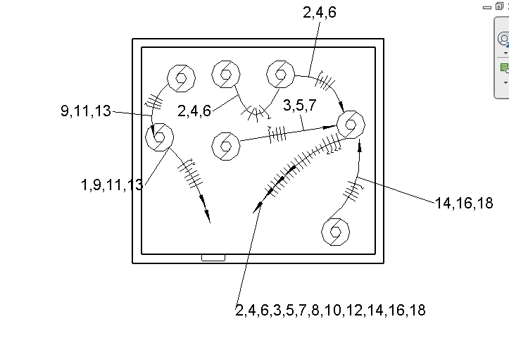
Unfortunately, that doesn't work. Here's a snapshot of what I want it to look like (done in ACAD).

I don't see this possible in Revit.
Shawn B.
||
To help improve Autodesk Products, please Click Here to Vote for ideas and submit your own.
To help improve Autodesk Products, please Click Here to Vote for ideas and submit your own.
Message 12 of 14
06-15-2013
04:08 PM
- Mark as New
- Bookmark
- Subscribe
- Mute
- Subscribe to RSS Feed
- Permalink
- Report
06-15-2013
04:08 PM
Well, You will have to wait a bit to get it like that. remember that Revit is not like Autocad. Autocad is a more mature project with more years in the market and with many improvements. Anyways, take care!
Message 13 of 14
06-15-2013
04:17 PM
- Mark as New
- Bookmark
- Subscribe
- Mute
- Subscribe to RSS Feed
- Permalink
- Report
06-15-2013
04:17 PM
Ok thanks for helping me look into it! Hopefully we see some changes soon for Revit. Maybe next year with the 2015 release.
Thanks,
Shawn
Sent from my iPhone
Thanks,
Shawn
Sent from my iPhone
Shawn B.
||
To help improve Autodesk Products, please Click Here to Vote for ideas and submit your own.
To help improve Autodesk Products, please Click Here to Vote for ideas and submit your own.
Message 14 of 14
06-24-2013
05:57 PM
- Mark as New
- Bookmark
- Subscribe
- Mute
- Subscribe to RSS Feed
- Permalink
- Report
06-24-2013
05:57 PM
Pleaes go to AUGI and help vote to incorporate 3-phase systems into Revit's next release! Autodesk pays more attention to AUGI than they do their own website.
http://forums.autodesk.com/t5/Autodesk-Revit-MEP/Help-make-the-E-Better-in-MEP/m-p/4304876#M19544
http://forums.autodesk.com/t5/Autodesk-Revit-MEP/Help-make-the-E-Better-in-MEP/m-p/4304876#M19544
Shawn B.
||
To help improve Autodesk Products, please Click Here to Vote for ideas and submit your own.
To help improve Autodesk Products, please Click Here to Vote for ideas and submit your own.
Reply
Topic Options
- Subscribe to RSS Feed
- Mark Topic as New
- Mark Topic as Read
- Float this Topic for Current User
- Bookmark
- Subscribe
- Printer Friendly Page

