Community
- Forums Home
- >
- Revit Products Community
- >
- Revit Architecture Forum
- >
- Re: Why a Floor Plan's View Range is illogical and puts off new users
Revit Architecture Forum
Welcome to Autodesk’s Revit Architecture Forums. Share your knowledge, ask questions, and explore popular Revit Architecture topics.
Turn on suggestions
Auto-suggest helps you quickly narrow down your search results by suggesting possible matches as you type.
Why a Floor Plan's View Range is illogical and puts off new users
6 REPLIES 6
Reply
Topic Options
- Subscribe to RSS Feed
- Mark Topic as New
- Mark Topic as Read
- Float this Topic for Current User
- Bookmark
- Subscribe
- Printer Friendly Page
Message 1 of 7
01-17-2013
01:47 PM
- Mark as New
- Bookmark
- Subscribe
- Mute
- Subscribe to RSS Feed
- Permalink
- Report
01-17-2013
01:47 PM
Why a Floor Plan's View Range is illogical and puts off new users
Having been on Revit for more than 8 years there's nothing more difficult to explain to a new user than how the View Range functions. It's one of the first features one must deal with with Revit and yet it can yield illogical results without proper use. The #1 youtube video on Revit's View Range is 20 MINUTES long! Do things need to be that complicated?!
Here's my top reasons why View Range is illogical:
1. It does not behave like the "view range" of all other Revit view types. Sections, Elevations, 3d views are all based on a simple concept, a direction, and a 3 dimensional bounding box. With floor plans, elements can appear (or not appear) in a floor plan that is clearly cut so that they shouldn't if the user doesn't understand the rules (and there are lots).
2. It has "Additional View Range Rules" (or exceptions to logic), 7 in fact, which takes Revit Wiki over a page to describe. Each rule is complicated and very situational. No other Revit view types have exceptions. Why floor plans need to have special exceptions is absurd and political. These exceptions must also slow down regeration time of the model since it must process different groups of elements individually to determine their view state in the floor plan.
3. Modern architecture does not adhere to simple boxy shapes and user's need to trust that their view range is actually cutting the surface as they see it. No exceptions or special rules.
4. View Range has a Top and a Cutting Plane elevation. It is completely illogical for any element to appear above the cutting plane. This can easily lead to misinterpretation of 2d drawings because some elements may not appear in section even though they are above the cutting plane. Views should have a cutting plane, direction (up or down in this case) and a depth. Simple, just like all other Revit views.
5. The View Depth "range" is rarely used effectively. The only practical use is to show low roofs of buildings with higher roofs, or possibly foundation elements. Scope boxes or Underlays can accomplish this task much simpler. All the additional line-styles that accompany View Depths are just unnecessary and add more things for the user to manage. It's time to kill View Depth.
It's in Autodesk's best interest to make Revit a user-friendly application. This is one area that needs attention. Keep Revit easy to use without having to watch a 20 minute video.
6 REPLIES 6
Message 2 of 7
01-17-2013
02:19 PM
- Mark as New
- Bookmark
- Subscribe
- Mute
- Subscribe to RSS Feed
- Permalink
- Report
01-17-2013
02:19 PM
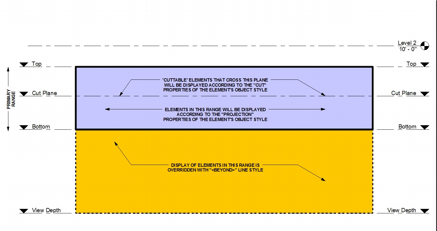
This diagram explains it fairly well.....see attached.
Cliff B. Collins
Registered Architect/BIM Manager
Thalden Boyd Emery Architects
St. Louis, MO
Registered Architect/BIM Manager
Thalden Boyd Emery Architects
St. Louis, MO
Message 3 of 7
01-17-2013
02:52 PM
- Mark as New
- Bookmark
- Subscribe
- Mute
- Subscribe to RSS Feed
- Permalink
- Report
01-17-2013
02:52 PM
I totally understand how the View Range works and I agree the image depicts the primary zones of the View Range. It does not however discuss the numerous exceptions and caveats to these rules.
My argument is that View Range should function like all other Views in Revit, with no exceptions.
Message 4 of 7
10-17-2013
03:35 AM
- Mark as New
- Bookmark
- Subscribe
- Mute
- Subscribe to RSS Feed
- Permalink
- Report
10-17-2013
03:35 AM
Another illogical thing is that bottom range doesn't automatically change when you change the view depth. Instead of telling me that the bottom range can't be below the view range, just change it to the same value as the view depth or change the view depth to the same value as the bottom range?
Message 5 of 7
10-17-2013
10:08 AM
- Mark as New
- Bookmark
- Subscribe
- Mute
- Subscribe to RSS Feed
- Permalink
- Report
10-17-2013
10:08 AM
I totally agree, this is something I need to look up all the time.
Especially elements that get covered by the wall, like windows and doors.
on a floor plan I want to show doors and windows. If I have a window with sill height 1' that is $'high and a clerestory window... then something always won't show up.
Revit version: R2024.2
Message 6 of 7
04-02-2014
02:32 PM
- Mark as New
- Bookmark
- Subscribe
- Mute
- Subscribe to RSS Feed
- Permalink
- Report
04-02-2014
02:32 PM
Unfortunately, maybe due to these additional rules that are mentioned here, this graphic doesn't really describe how it works. It simply describes how it should work, but I'm have problems showing stairs the way I'd like to show them. And follow this graphic (and the help files') logic, View Range is not working correctly. If I don't finsd a good answer, I'm probably starting another thread on this... It's too bad something this simple doesn't seem to work even in a blank new project template.
Message 7 of 7
04-02-2014
04:48 PM
- Mark as New
- Bookmark
- Subscribe
- Mute
- Subscribe to RSS Feed
- Permalink
- Report
04-02-2014
04:48 PM
I realize that the original post is mostly rhetorical or at least airing an opinion for discussion. This reply isn't meant to deny or counter its claims, rather it is for the sake of someone wandering into the thread lacking some background...
While it eludes a simple elevator pitch explanation it (View Range) allows Revit to display elements according to as many as three distinct line weight assignments based on where they happen to exist within vertical space (one at the cut plane - Cut, another within the primary range - Projection and a third "Beyond" - built in linestyle).
It's been my experience that for the majority of plan views the default settings don't really need to be altered. In beginner training sessions it only really becomes obvious or necessary to dig into View Range settings at all when people see the default Ceiling Plan views don't indicate where door or window openings are.
- For a mezzanine below we only need to increase (use a negative value or deeper setting) the View Depth setting of a floor plan to show the lower floor with the Beyond linestyle.
- Roof below is similar to a mezzanine condition
- Split level plans where the offset is a matter of a few feet and we want the plan to look as if both levels are the "same", we need to change both Bottom (Primary Level) and View Depth so that the Projection lineweight is used instead of linestyle Beyond.
- Plan Regions are intended to let us show hosted elements like windows and doors as if they are at the same elevation as other doors/windows when they really are not, and as a result are not cut by the view's cut plane.
- For ceiling plans, an atrium above is the same as a mezzanine/roof below but in the reverse direction, View Upth instead of View Depth 🙂
FWIW, I've also created/shared four shorter videos (3-5 minutes each) about View Range focused on view orientation and specific conditions.
My other older self here: http://forums.autodesk.com/t5/user/viewprofilepage/user-id/46056
Reply
Topic Options
- Subscribe to RSS Feed
- Mark Topic as New
- Mark Topic as Read
- Float this Topic for Current User
- Bookmark
- Subscribe
- Printer Friendly Page

