- Subscribe to RSS Feed
- Mark Topic as New
- Mark Topic as Read
- Float this Topic for Current User
- Bookmark
- Subscribe
- Printer Friendly Page
- Mark as New
- Bookmark
- Subscribe
- Mute
- Subscribe to RSS Feed
- Permalink
- Report
I have a problem with bringing an Inventor model into Revit. It's not the import of the model that's the problem, but the way the model displays in Revit. (It displays fine in AutoCAD, 3ds max etc - just not Revit.)
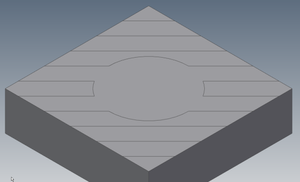
Here's the part file in Inventor - it's just a simple box with a couple of split-face features on it to generate a pattern.
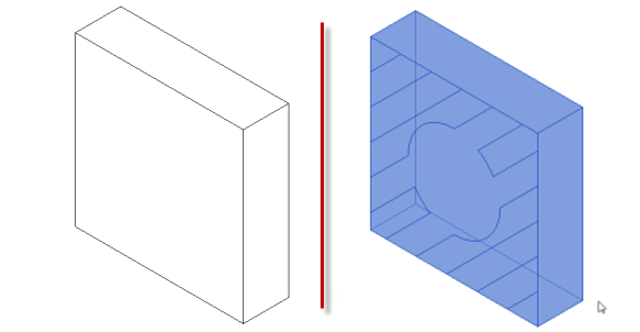
If I take the model into Revit, I can only see the pattern if I select the object.
Deselect the object and the pattern vanishes.
Here's an unselected/selected screenshot from Revit:
Models attached - Inventor 2014 IPT and a SAT version of the same.
Has anyone seen this before, and if so, how on earth did you solve it?
Thanks in advance.
Peter
Solved! Go to Solution.
Solved by constantin.stroescu. Go to Solution.
- Mark as New
- Bookmark
- Subscribe
- Mute
- Subscribe to RSS Feed
- Permalink
- Report
First off, this is a very clear well put-together post. Kudos for that.
I toyed around with the .SAT file and was able to reproduce your issue, but unfortunately, was not fortunate enough to have come up with a direct solution. In experimenting, I exploded the import and as a result, that surface pattern was created as Shapes; which means (I believe) that Revit interpreted the split regions and separate extrusion faces, and since the faces are exactly flush and parallel, the lines are not visible.
I don't have Inventor to test this, but can you export it to a DWG file and them import that? I imagine that you'd get the same results, though. If that is to no avail, then perhaps there is another means of creating the Split Face in Inventor, perhaps by applying it as a very subtlety offset extrusion for example. I'm not proficient with Inventor, so I can't really provide any suggestions beyond that.
- Mark as New
- Bookmark
- Subscribe
- Mute
- Subscribe to RSS Feed
- Permalink
- Report
Try this:
- the 3d imported object contains a series of coplanar faces (as Corey remarked), being coplanar the conection line does not appear. So, Revit recognise the shapes as faces (using Query, Revit will define these entities) . But no edit posibilty in Project.....
- Because we speak about faces , a logical approach is to try to study them in a Mass Editor - so : Create New > Conceptual Mass
- in Mass Editor >Insert> Import CAD. - import the .sat file.
- Now positioning the mouse over the Face that contains the "faces", TAB until selecting them one by one...Mass editor sees them....and they can be used as base to Create Form (see Image 067) - extruded forms
- If you want not to extrude but to show only the lines between the faces: Select the 3 d imported object and from Modify >Explode >Full Explode. Modify >Model >Pick Lines......You will see that you can snap on the border of the faces
- Once finished the Mass Element , load it into the Project . It will keep the lines on it...
BIM Manager AGD
Your Name
- Mark as New
- Bookmark
- Subscribe
- Mute
- Subscribe to RSS Feed
- Permalink
- Report
Cory D - Thanks, I'll take kudos any way I can get it! (I know what it's like when the OP's assume you're psychic.)
You are right about the DWG. The Inventor Split tool is like the AutoCAD "imprint" command - it just divides a face into different 'areas' (don't want to call them 'regions' because that's something different again). Bringing that sort of data into Revit fails in exactly the same way.
constantin.stroescu - Wow. Thank you. There's a lot of work in that reply.
I think that - based on the input from two clear experts (I can barely spell Revit) the answer to this one is that, left in their current state, these split-faces are not going to appear.
I tried slightly thickening some of the faces in Inventor so that a "real" model edge appears (like Image 067 in constantin.stroescu post) and it works really well, but a job that takes 2 minutes in Inventor is now going to take 2 hours. (Or about 10 days extra work over the project.) The real application of this involves a pattern that is not just imprinted into a flat face, it rolls and flows over numerous compound surfaces.)
Right. Off to the Revit Idea Station! "Support display of face-edges" please.
If anyone does discover a "quick" solution - please post it as I still have a few weeks before this needs to take over my life.
Thanks again.
- Mark as New
- Bookmark
- Subscribe
- Mute
- Subscribe to RSS Feed
- Permalink
- Report
Actually, I'm not ready to abandon hope on this.
After experimenting with some other shapes from Inventor, I noticed that tangent-edges do appear in Revit. These are not "hard" model edges, so why do they display? All the fillets in the example below are "Smooth G2", so there aren't any hard tangent edges to display. Yet Revit displays them... but not my split faces.
The three images below show Inventor Part, Revit unselected, and Revit selected.
The shiny-blue brick-pattern in the middle of the cube is my split-face thing.
Can anyone identify the difference between these edge-types?
(Attached IPT, SAT and... RFA! I have learnt at least one thing on this journey!)
- Mark as New
- Bookmark
- Subscribe
- Mute
- Subscribe to RSS Feed
- Permalink
- Report
As we have a surface within a surface it is normal not to see the borders of inside shape if there is the same material ...but if the inside shape is from a diferent material it has to be seen...Have you any posibility to export the 3d element like AutoCAD does with layers ( a layer for the 3d element and a diferent layer for the inside shape)? . Revit has the posibility to see and override the colors of layers on imported dwg files...
I made a test without having layers ( which I think can simplify the problem):
In Mass Editor (as shown in my previous post ) you can force the shape to appear , select it and visualise the borders.....
- New > Conceptual Mass>Insert >Import CAD - import the .sat file.
- select the shape by pieces using TAB and CTRL so to add to selection all the pieces of the shape
- then : Modify /Imports in Family > Divide Surface - as seen in Image 082 ( here it is shown applied only to two pieces not to the whole ensemble , in order to be more explicit)
BIM Manager AGD
Your Name
- Mark as New
- Bookmark
- Subscribe
- Mute
- Subscribe to RSS Feed
- Permalink
- Report
in my previous post at point 3, a correction:
Modify /Imports in Family > Divide Surface >Surface
BIM Manager AGD
Your Name
- Mark as New
- Bookmark
- Subscribe
- Mute
- Subscribe to RSS Feed
- Permalink
- Report
constantin - You are a legend. Thank you.
It was the suggestion of Layers that got me thinking. By exporting from Inventor to AutoCAD, I ran the XEDGES commands which extracts the edges of a 3D solid to a new layer. Bingo! One solid body, and one set of lines that defines all the edges. The beauty of this is that you can delete all the tangent edges you don't want to see. The only issue I discovered is that when a DWG file contains ACIS bodies and wireframe, you HAVE to specify the appropriate units in the import dialog box, otherwise you get an error about unsupported ACIS bodies.
Anyway - thanks for saving a ridiculous amount of time on the project.
- Subscribe to RSS Feed
- Mark Topic as New
- Mark Topic as Read
- Float this Topic for Current User
- Bookmark
- Subscribe
- Printer Friendly Page


