- Forums Home
- >
- Revit Products Community
- >
- Revit Architecture Forum
- >
- Re: Extrude profile that is rotated from plane?
- Subscribe to RSS Feed
- Mark Topic as New
- Mark Topic as Read
- Float this Topic for Current User
- Bookmark
- Subscribe
- Printer Friendly Page
- Mark as New
- Bookmark
- Subscribe
- Mute
- Subscribe to RSS Feed
- Permalink
- Report
Is there a work around to extruding a profile that is not parallel to the plane on the path. Im new to revit and want to create a componet the way I did in AutoCAD when I could just Extrude a closed poly with a path and it did not care it it was perpendicular to the path. Thanks
Solved! Go to Solution.
Solved by loboarch. Go to Solution.
- Mark as New
- Bookmark
- Subscribe
- Mute
- Subscribe to RSS Feed
- Permalink
- Report
The simple answer to the question is "no" an extrusion in Revit takes a profile and extrudes it perpendicular to the plane the profile was drawn in.
That being said there may be a way to create what you are looking for in Revit but it is hard to say without an example. A blend may be able to create what you are looking for? The massing tools will allow for just about any shape you might need but massing might not be what you want for this item depending on what you are making.
If you elaborate on what you are attempting to make and perhaps provide an example it might open up the possibilities for a solution.
- Mark as New
- Bookmark
- Subscribe
- Mute
- Subscribe to RSS Feed
- Permalink
- Report
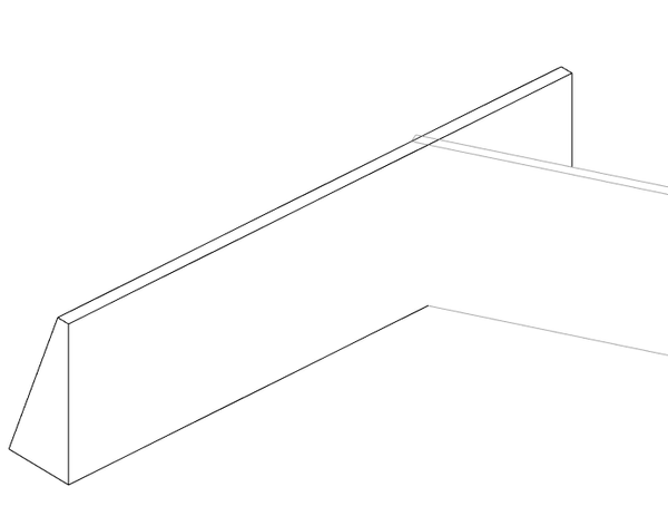
So I have a couple images of what Im trying to do in revit. What I did was use AutoCAD to draw a rectangular solid with one side sloped (Left, image 1) then with UCS set to face (back face) drew new closed poly and extruded it along a path. The trouble Im having in revit is that I can not easily get the batter angle of the right wall.
- Mark as New
- Bookmark
- Subscribe
- Mute
- Subscribe to RSS Feed
- Permalink
- Report
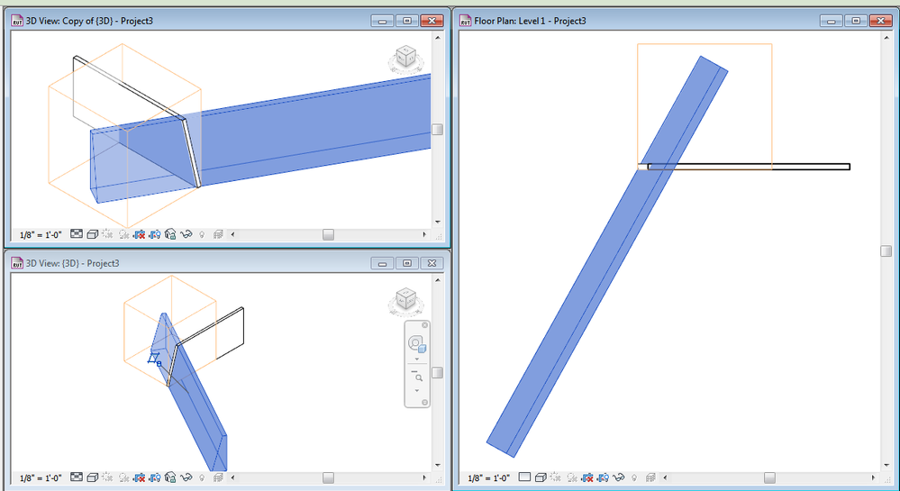
I think in this case it is probably going to be easiest to create the battered wall with a simple sweep which extends beyond where you need it and then use voids/cut geometry in order to cut the sweep at the angle you need it. I used this method to try and recreate the condition you were showing. The battered wall geometry was created with a sweep that extened beyond the wall with the sloped end. Then I used a void to "cut off" the excess. (orange box in the images). This lets you get the face at the end to be at whatever angle you need. You just draw the void geometry in the correct position.
- Mark as New
- Bookmark
- Subscribe
- Mute
- Subscribe to RSS Feed
- Permalink
- Report
Nice! How did you draw the "Profile" with the exact batter? Can you please give me some detail on that? Is there a snaps option Im missing? Im new to revit if you cant tell. Thanks.
- Mark as New
- Bookmark
- Subscribe
- Mute
- Subscribe to RSS Feed
- Permalink
- Report
I would recommend creating a Mass, and then attaching walls to the faces of the Mass for a shape like this.
Take a look at using the Conceptual Massing tools.
PS--Until Jeff convinces the Factory to give us the Tilt Wall Tool!!!! ![]()
- Mark as New
- Bookmark
- Subscribe
- Mute
- Subscribe to RSS Feed
- Permalink
- Report
Awww come on Cliff give me a break! ![]()
Cliff's recomendation of using a mass and then using the wall by face tool can work as well. I will elaborate on how I got the matching angle on my example.
- I edited the profile of a standard Revit wall to get the sloped end.
- Then I created an in place family using the category of wall (I assume these elements are walls)
- I Created a piece of geometry for the batttered wall uysing the sweep tool. I extended the sweep path beyond the end of the first wall. This is what I am going to cut off with the viod element. The plane I am going to need to sketch my profile on is in the middle and perpendicular to the path, that is ok.
- Now I will draw the profile for the sweep. To get the battered face to match the end of the first wall exactly I will use the "pick lines" option from the draw panel. This will project the angled line to the workplane of the profile sketch. Then I comple the loop for the profile sketch. and finish the sweep.
- Now from a top view I will create a simple void extrusion that cuts off the end I don't need. Then finish the model.
I hope this helps explain the entire process.
- Mark as New
- Bookmark
- Subscribe
- Mute
- Subscribe to RSS Feed
- Permalink
- Report
Yet another way to do it, is to create a family with the generic adaptive template. Draw the shape of the base of the wall at the reference level. Create a named reference plane for the top, and draw the shape of the top of the wall at that plane. Then Create form, and Load into project.
Alfredo Medina _________________________________________________________________ ______
Licensed Architect (Florida) | Freelance Instructor | Autodesk Expert Elite (on Revit) | Profile on Linkedin
- Mark as New
- Bookmark
- Subscribe
- Mute
- Subscribe to RSS Feed
- Permalink
- Report
There is always more than one way to skin a cat.
- Subscribe to RSS Feed
- Mark Topic as New
- Mark Topic as Read
- Float this Topic for Current User
- Bookmark
- Subscribe
- Printer Friendly Page


