Community
- Forums Home
- >
- Revit Products Community
- >
- Revit Architecture Forum
- >
- Re: 'Cut Structural Member with Plane' not working as detailed in wiki
Revit Architecture Forum
Welcome to Autodesk’s Revit Architecture Forums. Share your knowledge, ask questions, and explore popular Revit Architecture topics.
Turn on suggestions
Auto-suggest helps you quickly narrow down your search results by suggesting possible matches as you type.
'Cut Structural Member with Plane' not working as detailed in wiki
5 REPLIES 5
Reply
Topic Options
- Subscribe to RSS Feed
- Mark Topic as New
- Mark Topic as Read
- Float this Topic for Current User
- Bookmark
- Subscribe
- Printer Friendly Page
Message 1 of 6
09-11-2013
01:43 AM
- Mark as New
- Bookmark
- Subscribe
- Mute
- Subscribe to RSS Feed
- Permalink
- Report
09-11-2013
01:43 AM
'Cut Structural Member with Plane' not working as detailed in wiki
I'm trying to use the information given in the 'Cut Structural Member with Plane' topic in the wiki (http://wikihelp.autodesk.com/Revit/enu/2013/Help/00001-Revit_He0/2760-Tools_an2760/2812-Editing_2812...), but it does not seem to work as advertised.
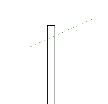
The element I am trying to cut is a family instance I have constructed myself, based on the Generic Model template. I have inserted the reference plane as instructed (see attached image).
Whilst the Cut Geometry function has no problem accepting my element as the element to cut, Revit then asks me to select the Family Instance to cut with. According to the wiki, I should be able to select the reference plane - which is exactly what I want, to add a custom cut angle to the component. Needless to say the software won't let me select the plane as the family instance.
Any idea if I'm doing something wrong? I did find an entry on here mentioning generic models but unfortunately it received no answer at the time. I hope to have better luck!
5 REPLIES 5
Message 2 of 6
09-11-2013
12:01 PM
- Mark as New
- Bookmark
- Subscribe
- Mute
- Subscribe to RSS Feed
- Permalink
- Report
09-11-2013
12:01 PM
Hello -
I gave it a try and did not have any issues...
I reread your post and the thing that jumps out to me is the generic model...
So I went and put a column in, and then created one from a generic model and put it in...
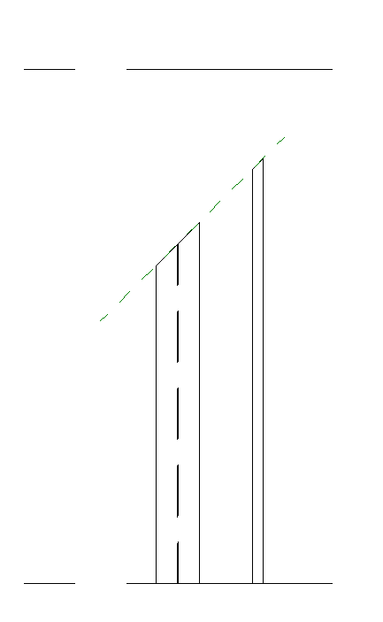
I did the cut with the reference plane and could cut the OTB column - mine would not cut..
It is because it is a generic model... Once I change it to a structural column - I could cut it. Image attached.
So you need to change the Family Category and then you will be able to cut it with a reference plane.
LD
If this helped solve your issue - remember to 'accept as solution' to help other find answers!
You can't think AutoCAD and run Revit.
Email: LisaDragoEE@gmail.com
Message 3 of 6
09-12-2013
12:50 AM
- Mark as New
- Bookmark
- Subscribe
- Mute
- Subscribe to RSS Feed
- Permalink
- Report
09-12-2013
12:50 AM
Thank you for your reply.
The problem with basing our family on a column or any other named type is that that type's template starts with prefined parameters and behaviour that restricts free use of the element in the drawing (perhaps for good reason, but that is a matter of debate). Because I am trying to design this family to allow us to export our AutoCAD-based models into IFC format for Revit to import, we need to be able to represent our model elements (custom objects) in a way that is as freeform as possible, so that as much of the flexibility in our AutoCAD model's objects as possible can be emulated in Revit - otherwise importing the model into Revit would be of little use to the customer.
If the answer is 'you can't cut a generic model with a reference plane' then my question [for the Revit development team] is why? This is an extruded solid, so it has physical form just like a column or anything else - why can't a plane be used to cut such a solid in the same way as it can cut a column?
A better question for now is, how *can* I apply a cut to a generic model? I cannot believe it is not possible. I do not understand why such heavy restrictions have been placed on Revit objects and why there is such inconsistency.
Message 4 of 6
09-12-2013
02:19 AM
- Mark as New
- Bookmark
- Subscribe
- Mute
- Subscribe to RSS Feed
- Permalink
- Report
09-12-2013
02:19 AM
Let me rephrase that last question: How can I specify a cut to be made on an element (from a family based on the Generic Model family) - a cut that completely removes the end of the element - in a way that can be specified in an IFC file (so that when Revit loads the model, it sees the 'cut' instruction / object and applies the cut to the model based on the parameters).
Message 5 of 6
09-12-2013
02:49 AM
- Mark as New
- Bookmark
- Subscribe
- Mute
- Subscribe to RSS Feed
- Permalink
- Report
09-12-2013
02:49 AM
Having already the family made as Generic Model I suggest to open it and make a parametric Void and Cut your element with it. Check the option :Cut with Voids when Loaded and then Load it into the project...
I"ve attached a rough example of such a family...


Constantin Stroescu
BIM Manager AGD
BIM Manager AGD
Your Name
Message 6 of 6
06-09-2020
05:57 PM
- Mark as New
- Bookmark
- Subscribe
- Mute
- Subscribe to RSS Feed
- Permalink
- Report
06-09-2020
05:57 PM
Hello,
can anyone please help me in providing the step wise tutorial?
I checked the link provided above but it did not show.
Thank you in advance.
Reply
Topic Options
- Subscribe to RSS Feed
- Mark Topic as New
- Mark Topic as Read
- Float this Topic for Current User
- Bookmark
- Subscribe
- Printer Friendly Page

