Community
Inventor Forum
Welcome to Autodesk’s Inventor Forums. Share your knowledge, ask questions, and explore popular Inventor topics.
Turn on suggestions
Auto-suggest helps you quickly narrow down your search results by suggesting possible matches as you type.
Reply
Topic Options
- Subscribe to RSS Feed
- Mark Topic as New
- Mark Topic as Read
- Float this Topic for Current User
- Bookmark
- Subscribe
- Printer Friendly Page
Message 1 of 6
05-23-2005
12:38 PM
- Mark as New
- Bookmark
- Subscribe
- Mute
- Subscribe to RSS Feed
- Permalink
- Report
05-23-2005
12:38 PM
Welding to curved surfaces
I am looking to properly represent the way we weld pad eyes on to pipe. In our process we place the base of the padeye tangent to the pipe and fillet weld it to the pipe. I have found several work around's but this will not properly analyses when I pass the model to out FEA program. Does any one have any insight?
5 REPLIES 5
Message 2 of 6
05-23-2005
02:21 PM
- Mark as New
- Bookmark
- Subscribe
- Mute
- Subscribe to RSS Feed
- Permalink
- Report
05-23-2005
02:21 PM
Will the emboss tool give you what you need?
wrote in message news:4853802@discussion.autodesk.com...
I am looking to properly represent the way we weld pad eyes on to pipe. In
our process we place the base of the padeye tangent to the pipe and fillet
weld it to the pipe. I have found several work around's but this will not
properly analyses when I pass the model to out FEA program. Does any one
have any insight?
Message 3 of 6
05-23-2005
02:23 PM
- Mark as New
- Bookmark
- Subscribe
- Mute
- Subscribe to RSS Feed
- Permalink
- Report
05-23-2005
02:23 PM
I don't think so. It would probably give the visual representation, but not the physical properties I will need.
Message 4 of 6
05-23-2005
04:02 PM
- Mark as New
- Bookmark
- Subscribe
- Mute
- Subscribe to RSS Feed
- Permalink
- Report
05-23-2005
04:02 PM
Hi Mark,
I've put an example in customer-files (using the same subject). First I
made a weldment assembly using the groove weld tool to get the desired bead
geometry. Please examine the padeye component and note the split features I
used to define the bead surfaces and the work features that control the
beads fill direction. After this I created a new part and derived in the
weldment. The FEA was performed on the derived assembly in Inventor 10
professional. I'm not sure if this will be successful in your FEA software,
or even if I did it accurately. However, it might give you some news ideas
on how to get around the fillet tool limitation.
Regards,
Harold Lee
Inventor QA
Message 5 of 6
05-24-2005
07:28 AM
- Mark as New
- Bookmark
- Subscribe
- Mute
- Subscribe to RSS Feed
- Permalink
- Report
05-24-2005
07:28 AM
Thanks for the work around. It is a bit of work but will give me what I need. Is there any plan to add the ability for the fillet weld to work with flat to curved surfaces?
Message 6 of 6
05-24-2005
09:21 AM
- Mark as New
- Bookmark
- Subscribe
- Mute
- Subscribe to RSS Feed
- Permalink
- Report
05-24-2005
09:21 AM
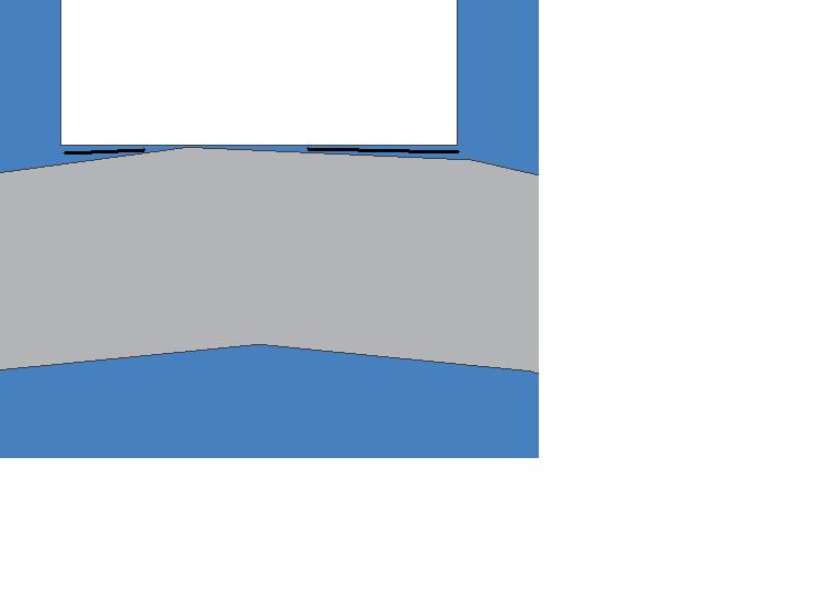
Hi Mark,
Currently fillet welds handle hole gaps well. (For example: cylinder going through a block which has a hole in it)
I took a look at this case and it has a gap between the two components. The side view image is attached and gap is shown as black lines. Fillet welds don't handle this kind of gap currently.
Gap and groove welds like Harold demonstrates is the recommended solution for this kind of gap case. Thanks.
shekar
PS: I have posted examples on fillet with gap in this NG. Please search if you need additional information.
Reply
Topic Options
- Subscribe to RSS Feed
- Mark Topic as New
- Mark Topic as Read
- Float this Topic for Current User
- Bookmark
- Subscribe
- Printer Friendly Page
