Community
- Forums Home
- >
- Inventor Community
- >
- Inventor Forum
- >
- Possible mistakes in the tutorial "Extrude the Two Sketch Profiles" for 2012?
Inventor Forum
Welcome to Autodesk’s Inventor Forums. Share your knowledge, ask questions, and explore popular Inventor topics.
Turn on suggestions
Auto-suggest helps you quickly narrow down your search results by suggesting possible matches as you type.
Possible mistakes in the tutorial "Extrude the Two Sketch Profiles" for 2012?
12 REPLIES 12
SOLVED
Reply
Topic Options
- Subscribe to RSS Feed
- Mark Topic as New
- Mark Topic as Read
- Float this Topic for Current User
- Bookmark
- Subscribe
- Printer Friendly Page
Message 1 of 13
04-08-2011
09:33 AM
- Mark as New
- Bookmark
- Subscribe
- Mute
- Subscribe to RSS Feed
- Permalink
- Report
04-08-2011
09:33 AM
Hello. I have been trying to follow the steps in this tutorial for hours. There have been no success. After choosing Extrude in Step.1, how do I select the two sketch profiles listed in Step.2? I cannot select two profiles at the same time. I tried to swap the steps. i.e., First, click sketch2 which includes both scretches made in previuos steps. Then, right click and choose Extrude. However, I cannot extrude both the upper and lower profiles. Moreover, I cannot change the option from Join to Cut as indicated in Steps. 3 and 4. Moreover, Step.5 mentions that the graphical preview changes color from gree to red to indicate the Cut option. There is no green nor red on the screen. Could anybody please check this part of the tutorial? I just can't follow the steps from 2 to the end. Thanks.
Solved! Go to Solution.
Solved by JDMather. Go to Solution.
12 REPLIES 12
Message 2 of 13
04-08-2011
09:48 AM
- Mark as New
- Bookmark
- Subscribe
- Mute
- Subscribe to RSS Feed
- Permalink
- Report
04-08-2011
09:48 AM
Attach your ipt file here.
-----------------------------------------------------------------------------------------
Autodesk Inventor 2019 Certified Professional
Autodesk AutoCAD 2013 Certified Professional
Certified SolidWorks Professional
Message 3 of 13
04-08-2011
09:48 AM
- Mark as New
- Bookmark
- Subscribe
- Mute
- Subscribe to RSS Feed
- Permalink
- Report
04-08-2011
09:48 AM
Thanks for the reply. It is under:
WikiHelp>Inventor>English>2012>Help>Tutorials>Inventor Tutorials>Direct Manipulation>Extrude the Two Sketch Profiles
I cannot reproduce the following. I followed the steps but there seems to be mistakes from Step.2 on.
Message 4 of 13
04-08-2011
09:53 AM
- Mark as New
- Bookmark
- Subscribe
- Mute
- Subscribe to RSS Feed
- Permalink
- Report
04-08-2011
09:53 AM
The name of the tutorial is Direct Manipulation.
Attach your ipt file here.
-----------------------------------------------------------------------------------------
Autodesk Inventor 2019 Certified Professional
Autodesk AutoCAD 2013 Certified Professional
Certified SolidWorks Professional
Message 6 of 13
04-08-2011
10:10 AM
- Mark as New
- Bookmark
- Subscribe
- Mute
- Subscribe to RSS Feed
- Permalink
- Report
04-08-2011
10:10 AM
Sketch1 is unconstrained - somehow you just missed the origin. You can drag it away from the origin and back (watch for green snap).
In any case you got your arc drawn in Sketch2 - but it is incorrect.
When you click your sketch notice that it defaults to Surface Output.
Click on Solid instead of Surface
Expand the dialog box if they told you to collapse it.
Click on the Red Cross.
You might just do better to erase and redraw the sketch rather than trying to figure out the Sketch Doctor.
______________
Can someone show me how to get the arc tangent to that phantom line rather than to the sketch line as shown in attached image?
Well I got it now. Is this new in 2012?
-----------------------------------------------------------------------------------------
Autodesk Inventor 2019 Certified Professional
Autodesk AutoCAD 2013 Certified Professional
Certified SolidWorks Professional
Message 7 of 13
04-08-2011
07:18 PM
- Mark as New
- Bookmark
- Subscribe
- Mute
- Subscribe to RSS Feed
- Permalink
- Report
04-08-2011
07:18 PM
Thank you very much for your help. I am very sorry but as a beginner, I am at a lost. Could you please walk me through step by step?
>Sketch1 is unconstrained - somehow you just missed the origin. You can drag it away from the origin and back (watch for >green snap).
I downloaded Sketch1 from Autodesk's website. Do you mean the model provided by Autodesk should have been constrained (coincident) to the origin? Why it is required to constrain Sketch1 to the origin?
>In any case you got your arc drawn in Sketch2 - but it is incorrect.
I am a bit confused. I created Work Plane 1 in "Create an Offset Parallel Work Plane". Then, in "Create a New Sketch", I created Sketch2. Next, in "Project Geometry onto the Sketch Plane", Step.2, I selected the top horizontal line, the arc representing the spherical radius (do you mean this arc?) and the x-axis. Do you mean I made mistake in this step?
>When you click your sketch notice that it defaults to Surface Output.
>Click on Solid instead of Surface
Which sketch do you mean? Could you please tell me how I can tell that the sketch defaults to Surface Output?
In the tutorial (the window on the left of the screen shot in the attachment), there are two red arrows pointing to the top horizontal line and the arc. I enclosed a screen shot of what I have done at the end of Step.3. When you wrote "Click on Solid instead of Surface", do you mean I got Step.2 wrong?
Message 8 of 13
04-09-2011
04:38 AM
- Mark as New
- Bookmark
- Subscribe
- Mute
- Subscribe to RSS Feed
- Permalink
- Report
04-09-2011
04:38 AM
The problem with Sketch1 has nothing to do with the problem you are experiencing in this case.
It is simply professional practice to fully constrain most, if not every sketch.
You can check for a fully constrained sketch in several ways - look in bottom right corner of screen for one indication.
Another indication is that the sketch will change color (although this might not tell the whole story).
Forget about Sketch1 for now - it really has nothing to do with the problem you are experiencing.
Sketch2
You correctly projected the lines and arcs as indicated in the tutorial.
If I had written the tutorial I would have had you change those projected entities to Construction linetype.
You correctly drew the lines in the earlier file you attached.
But the short arc was somehow incorrectly drawn (I didn't investigate exactly what the problem was - but my guess would be snap points to the lines or multiple small arcs).
The file you just posted is correct up to the step where you draw the lines and arc. Go ahead and draw these again and then try to extrude or attach the file here.
-----------------------------------------------------------------------------------------
Autodesk Inventor 2019 Certified Professional
Autodesk AutoCAD 2013 Certified Professional
Certified SolidWorks Professional
Message 9 of 13
04-10-2011
01:47 AM
- Mark as New
- Bookmark
- Subscribe
- Mute
- Subscribe to RSS Feed
- Permalink
- Report
04-10-2011
01:47 AM
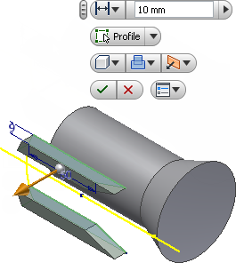
The tutorial is written to teach specific skills and is technically correct as far as I can see, but there are other, perhaps easier and better techniques to get the same geometry.
In general it is better practice to mirror or pattern features rather than sketches.
You really only need to sketch two lines to make that extrude cut, and then mirror or revolve to other side. (see attached).
You should be able to do it both ways. Post back if you can't figure out one or the other.
-----------------------------------------------------------------------------------------
Autodesk Inventor 2019 Certified Professional
Autodesk AutoCAD 2013 Certified Professional
Certified SolidWorks Professional
Message 11 of 13
04-22-2014
12:50 AM
- Mark as New
- Bookmark
- Subscribe
- Mute
- Subscribe to RSS Feed
- Permalink
- Report
Message 12 of 13
04-22-2014
03:12 AM
- Mark as New
- Bookmark
- Subscribe
- Mute
- Subscribe to RSS Feed
- Permalink
- Report
04-22-2014
03:12 AM
What version of Inventor are you using?
What do you see when you go to HelP>Learning Tools>Tutorials?
-----------------------------------------------------------------------------------------
Autodesk Inventor 2019 Certified Professional
Autodesk AutoCAD 2013 Certified Professional
Certified SolidWorks Professional
Message 13 of 13
04-22-2014
04:06 AM
- Mark as New
- Bookmark
- Subscribe
- Mute
- Subscribe to RSS Feed
- Permalink
- Report
04-22-2014
04:06 AM
Im using Inventor 2013, I found the Tutorial he described, it wasnt that kind of tutorial i was looking for 🙂
Reply
Topic Options
- Subscribe to RSS Feed
- Mark Topic as New
- Mark Topic as Read
- Float this Topic for Current User
- Bookmark
- Subscribe
- Printer Friendly Page
