Community
Inventor Forum
Welcome to Autodesk’s Inventor Forums. Share your knowledge, ask questions, and explore popular Inventor topics.
Turn on suggestions
Auto-suggest helps you quickly narrow down your search results by suggesting possible matches as you type.
Reply
Topic Options
- Subscribe to RSS Feed
- Mark Topic as New
- Mark Topic as Read
- Float this Topic for Current User
- Bookmark
- Subscribe
- Printer Friendly Page
Message 1 of 15
04-26-2010
01:42 AM
- Mark as New
- Bookmark
- Subscribe
- Mute
- Subscribe to RSS Feed
- Permalink
- Report
04-26-2010
01:42 AM
Not sure how to constrain a CV Coupling.
For the past few weeks, I've been messing around with CV couplings in Inventor. Earlier tonight, I came up with a design for a coupling which is based off the concept of the Rzeppa coupling and should be able to deal with large shaft angles and torque loads without the thermal runaway issues Rzeppa couplings typically have. I decided to make a quick concept model in Inventor to see if it'd work, and then ran into some issues trying to add the proper constraints/joints in Inventor's dynamic simulator environment. If you open the assembly file and its associated part files that I've attached to this post, you'll notice between the Base Ring and the sphere at the tip of each Push-Pin that I've added a tangent constraint. This allows each Push-Pin to rotate inside the Base Ring and still transfer torque between the Base Ring and the Outer Ring. I tried rotating the assembly once all of the constraints were added, and of course, nothing happened. Perhaps not a good sign, but not sufficiently bad to deter me from trying to forcibly simulate the coupling's motion in the dynamic simulator. When I switched over to the dynamic simulation environment, it of course did not convent the tangent constraints into spherical constraints automatically, so I tried adding said constraints manually (after converting all of the assembly's axial constraints). This didn't happen, I'm not sure why. What I've concluded from this is that I do not know how to make Inventor's Dynamic Simulator transfer torque between to rotating shafts using spherical constraints. I want to know how to do this, so I'm hoping someone here might be able to help me.
Let me know if any parts are missing and I greatly appreciate your help!
-Alan Campbell
P.S. The Experimental Coupling assembly file was created in a larger project file entitled "Thompson Coupling", you may want to make that the base directory you extract the attached zip file into if you run into problems resolving part links. Also, there should only be two Push-Pins present in the assembly.
14 REPLIES 14
Message 2 of 15
04-26-2010
07:48 AM
- Mark as New
- Bookmark
- Subscribe
- Mute
- Subscribe to RSS Feed
- Permalink
- Report
04-26-2010
07:48 AM
Hi Alan,
I'ne not looked at the principle of the Rzeppa coupling, but your assembly
is unmovable, because of geometric restrictions.
Try to measure the distance between the half-ball elements and the axes of
the pins. You'll get no zero distance in most cases; zero only appears in a
special position.
That's why it's locking
Walter
schrieb im Newsbeitrag news:6380227@discussion.autodesk.com...
For the past few weeks, I've been messing around with CV couplings in
Inventor. Earlier tonight, I came up with a design for a coupling which is
based off the concept of the Rzeppa coupling and should be able to deal with
large shaft angles and torque loads without the thermal runaway issues
Rzeppa couplings typically have. I decided to make a quick concept model in
Inventor to see if it'd work, and then ran into some issues trying to add
the proper constraints/joints in Inventor's dynamic simulator environment.
If you open the assembly file and its associated part files that I've
attached to this post, you'll notice between the Base Ring and the sphere at
the tip of each Push-Pin that I've added a tangent constraint. This allows
each Push-Pin to rotate inside the Base Ring and still transfer torque
between the Base Ring and the Outer Ring. I tried rotating the assembly
once all of the constraints were added, and of course, nothing happened.
Perhaps not a good sign, but not sufficiently bad to deter me from trying to
forcibly simulate the coupling's motion in the dynamic simulator. When I
switched over to the dynamic simulation environment, it of course did not
convent the tangent constraints into spherical constraints automatically, so
I tried adding said constraints manually (after converting all of the
assembly's axial constraints). This didn't happen, I'm not sure why. What
I've concluded from this is that I do not know how to make Inventor's
Dynamic Simulator transfer torque between to rotating shafts using spherical
constraints. I want to know how to do this, so I'm hoping someone here
might be able to help me.
Let me know if any parts are missing and I greatly appreciate your help!
-Alan Campbell
P.S. The Experimental Coupling assembly file was created in a larger project
file entitled "Thompson Coupling", you may want to make that the base
directory you extract the attached zip file into if you run into problems
resolving part links. Also, there should only be two Push-Pins present in
the assembly.
I'ne not looked at the principle of the Rzeppa coupling, but your assembly
is unmovable, because of geometric restrictions.
Try to measure the distance between the half-ball elements and the axes of
the pins. You'll get no zero distance in most cases; zero only appears in a
special position.
That's why it's locking
Walter
For the past few weeks, I've been messing around with CV couplings in
Inventor. Earlier tonight, I came up with a design for a coupling which is
based off the concept of the Rzeppa coupling and should be able to deal with
large shaft angles and torque loads without the thermal runaway issues
Rzeppa couplings typically have. I decided to make a quick concept model in
Inventor to see if it'd work, and then ran into some issues trying to add
the proper constraints/joints in Inventor's dynamic simulator environment.
If you open the assembly file and its associated part files that I've
attached to this post, you'll notice between the Base Ring and the sphere at
the tip of each Push-Pin that I've added a tangent constraint. This allows
each Push-Pin to rotate inside the Base Ring and still transfer torque
between the Base Ring and the Outer Ring. I tried rotating the assembly
once all of the constraints were added, and of course, nothing happened.
Perhaps not a good sign, but not sufficiently bad to deter me from trying to
forcibly simulate the coupling's motion in the dynamic simulator. When I
switched over to the dynamic simulation environment, it of course did not
convent the tangent constraints into spherical constraints automatically, so
I tried adding said constraints manually (after converting all of the
assembly's axial constraints). This didn't happen, I'm not sure why. What
I've concluded from this is that I do not know how to make Inventor's
Dynamic Simulator transfer torque between to rotating shafts using spherical
constraints. I want to know how to do this, so I'm hoping someone here
might be able to help me.
Let me know if any parts are missing and I greatly appreciate your help!
-Alan Campbell
P.S. The Experimental Coupling assembly file was created in a larger project
file entitled "Thompson Coupling", you may want to make that the base
directory you extract the attached zip file into if you run into problems
resolving part links. Also, there should only be two Push-Pins present in
the assembly.
Message 3 of 15
04-26-2010
12:21 PM
- Mark as New
- Bookmark
- Subscribe
- Mute
- Subscribe to RSS Feed
- Permalink
- Report
04-26-2010
12:21 PM
Now I've played with the Rzeppa coupling.
If it's simplified to only two balls, it's moving well in assembly mode. If
more balls are involved, there's switching of positions 180 degrees
opposite, and sometimes calculation errors in drive by constraint mode.
;-) But I'd like to see a skilled expert moving it in DS environment.
Walter
If it's simplified to only two balls, it's moving well in assembly mode. If
more balls are involved, there's switching of positions 180 degrees
opposite, and sometimes calculation errors in drive by constraint mode.
;-) But I'd like to see a skilled expert moving it in DS environment.
Walter
Message 4 of 15
04-26-2010
03:12 PM
- Mark as New
- Bookmark
- Subscribe
- Mute
- Subscribe to RSS Feed
- Permalink
- Report
04-26-2010
03:12 PM
Howdy Walter, I guess this is the second time you've helped me with a CV coupling issue. I did finally make a functional thompson coupling and even joined to of them together to make a CV Right Angle Drive. Unfortunately, the rzeppa coupling file you uploaded was created in I'm guessing the non-beta version of Inventor 2011. Because I'm cheap/broke, and because I like having a non-educational version of Inventor (I am an engineering student, I can get an educational copy legitimately), I haven't yet upgraded to the production version of Inventor 2011. Still using Beta 3. I tried making a rzeppa coupling about a month ago after carefully observing an animation of one posted on Wikipedia. I noticed that all of the ball bearings have to be constrained in the same plane, so I came up with a fairly clever system that constrained the XZ origin planes of each of my coupling's bearings to one another. I then added transitional constraints between each bearing and the central hub they all slide over top of. Weirdly, this did actually work, albeit not in the Dynamic Simulator. But, if I moved the bearings more than maybe 20 degrees off from where they were before, Inventor would crash spectacularly. I'll download the educational version of Inventor 2011 in the next day or so and see how the rzeppa coupling you posted works. If you want, I can send you a copy of the Thompson Coupling CVRAD I made, it's fairly interesting to watch work.
http://discussion.autodesk.com/forums/thread.jspa?messageID=6369293」 <-- Here's the first functional Thompson Coupling I made. Basically cloned it from a YouTube video I saw. I'm sort of surprised no one (besides Gary T.) has ever commented on it, since I think, besides the Rzeppa coupling you just posted, it's the only functioning and publicly available sample of a CV coupling on the internet.
Alan Campbell
Message 5 of 15
04-26-2010
04:24 PM
- Mark as New
- Bookmark
- Subscribe
- Mute
- Subscribe to RSS Feed
- Permalink
- Report
04-26-2010
04:24 PM
Hi Walt and Alan,
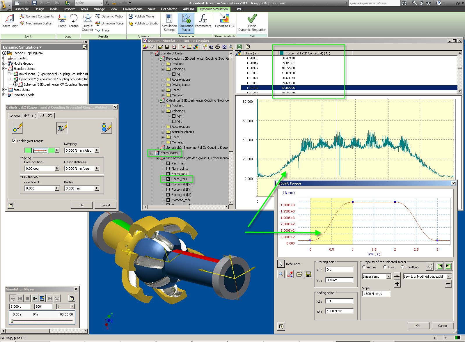
I was able to get the mechanism assembled and moving in Dynamic Simulation R2011 (see attached).
What I did was:
1) Unchecked "Automatically Convert Constraints to Standard Joints" in the Dynamic Simulation Settings dialog
2) Convert constraints between the Grounded Rings and the CV couplings to create a Revolution and Cylindrical Joints
3) Create a welded group between the two ball bearings and the "inner ball"
4) Create a 3D contact Joint between one of the ball bearings and the "outer cage"
Next, I created a constant input rotational velocity of 720 degrees / second. Then, to resist this force and simulate a ramping up, constant, ramping down resisting load I used the input grapher in the cylindrical joint's rotational DOF.
In the output grapher, I chose to display the force in the ball bearing exerted between the ball and the cage. As you can see, the curve shapes look very similar.
Now, if you compare the output, it should also be a constant 720 deg/sec but it is not. It varies sinusoidal from ~700 => 750 deg/s. I believe this is because we only have 1-2 ball bearings and it is basically reduced to something similar to a Universal or Cardan Joint.
I hope this helps to give a starting point of how we can simulate this type of mechanism in DS.
I wish I could upload the assembly file, but it is now 2.7 MB. I used WinRar and spanned "disks".
Hugh Henderson
QA Engineer (Fusion Simulation)
Message 6 of 15
04-26-2010
04:24 PM
- Mark as New
- Bookmark
- Subscribe
- Mute
- Subscribe to RSS Feed
- Permalink
- Report
04-26-2010
04:24 PM
Hi Walt and Alan,
I was able to get the mechanism assembled and moving in Dynamic Simulation R2011 (see attached).
What I did was:
1) Unchecked "Automatically Convert Constraints to Standard Joints" in the Dynamic Simulation Settings dialog
2) Convert constraints between the Grounded Rings and the CV couplings to create a Revolution and Cylindrical Joints
3) Create a welded group between the two ball bearings and the "inner ball"
4) Create a 3D contact Joint between one of the ball bearings and the "outer cage"
Next, I created a constant input rotational velocity of 720 degrees / second. Then, to resist this force and simulate a ramping up, constant, ramping down resisting load I used the input grapher in the cylindrical joint's rotational DOF.
In the output grapher, I chose to display the force in the ball bearing exerted between the ball and the cage. As you can see, the curve shapes look very similar.
Now, if you compare the output, it should also be a constant 720 deg/sec but it is not. It varies sinusoidal from ~700 => 750 deg/s. I believe this is because we only have 1-2 ball bearings and it is basically reduced to something similar to a Universal or Double Cardan Joint.
I hope this helps to give a starting point of how we can simulate this type of mechanism in DS.
I wish I could upload the assembly file, but it is now 2.7 MB. I used WinRar and spanned "disks".
Hugh Henderson
QA Engineer (Fusion Simulation)
Message 10 of 15
04-26-2010
11:03 PM
- Mark as New
- Bookmark
- Subscribe
- Mute
- Subscribe to RSS Feed
- Permalink
- Report
04-26-2010
11:03 PM
Ok, although I realize the topic of this post has now drifted pretty far off from what it once was, I've managed to make an 8 bearing Rzeppa coupling and have it work lag-lessly using a 3D Contact joint in Inventor's DS environment. Although I had to set the simulator fps count to over 2,000 to get good results, I have verified that what I've made is a true CV joint. It works a bit differently from the one you and Walter posted, it forces each bearing to rotate in the same plane. I've also opted not to make the bearings separate parts, rather I've just fused them to the outer cage. I think doing this drastically reduces the computational load on the simulator. The 8 bearings are constrained coupling's inner ball via a 3D contact joint, which for some amazing reason does not cause the simulation to lag at all. The assembly file I'm uploading has the four parts required to make the coupling and the parts' assembly file. The coupling in the assembly file cannot be moved outside of the dynamic simulator, it could at one point sort of, but when I posed it using the dynamic motion tool, everything went to hell and I had to suppress all of the tangent and transitional constraints that let it move in Inventor's assembly environment. One other thing of note, the bearings don't exactly fall into their grooves on the inner ball, this is mainly just due to me using an imprecise method of posing it. Although in real life this would be a disaster, this does not [significantly] effect the coupling's operation in the DS environment. Well, aside from what Walter just posted, I think this is the only functioning and publicly available model of a Rzeppa coupling...
Enjoy!
Alan Campbell
Enjoy!
Alan Campbell
Message 11 of 15
04-27-2010
12:08 AM
- Mark as New
- Bookmark
- Subscribe
- Mute
- Subscribe to RSS Feed
- Permalink
- Report
04-27-2010
12:08 AM
Thanks Alan,
I've your Test coupling (about April 11, 2010) here on my computer. I think
it's worth for looking deeper into it, but I didn't have much time left
then.
I'll do it now. But you're not really alone all around the world, in many
cases. Look here:
http://www.holzwarth-cad.net/images/images-wh/wmv/Thompson-Kupplung.wmv
Another thank to Hugh. I'll have to study his solution, and I think, I'll
come back later.
Walter
schrieb im Newsbeitrag news:6380787@discussion.autodesk.com...
Howdy Walter, I guess this is the second time you've helped me with a CV
coupling issue. I did finally make a functional thompson coupling and even
joined to of them together to make a CV Right Angle Drive. Unfortunately,
the rzeppa coupling file you uploaded was created in I'm guessing the
non-beta version of Inventor 2011. Because I'm cheap/broke, and because I
like having a non-educational version of Inventor (I am an engineering
student, I can get an educational copy legitimately), I haven't yet upgraded
to the production version of Inventor 2011. Still using Beta 3. I tried
making a rzeppa coupling about a month ago after carefully observing an
animation of one posted on Wikipedia. I noticed that all of the ball
bearings have to be constrained in the same plane, so I came up with a
fairly clever system that constrained the XZ origin planes of each of my
coupling's bearings to one another. I then added transitional constraints
between each bearing and the central hub they all slide over top of.
Weirdly, this did actually work, albeit not in the Dynamic Simulator. But,
if I moved the bearings more than maybe 20 degrees off from where they were
before, Inventor would crash spectacularly. I'll download the educational
version of Inventor 2011 in the next day or so and see how the rzeppa
coupling you posted works. If you want, I can send you a copy of the
Thompson Coupling CVRAD I made, it's fairly interesting to watch work.
http://discussion.autodesk.com/forums/thread.jspa?messageID=6369293」
<-- Here's the first functional Thompson Coupling I made. Basically cloned
it from a YouTube video I saw. I'm sort of surprised no one (besides Gary
T.) has ever commented on it, since I think, besides the Rzeppa coupling you
just posted, it's the only functioning and publicly available sample of a CV
coupling on the internet.
Alan Campbell
I've your Test coupling (about April 11, 2010) here on my computer. I think
it's worth for looking deeper into it, but I didn't have much time left
then.
I'll do it now. But you're not really alone all around the world, in many
cases. Look here:
http://www.holzwarth-cad.net/images/images-wh/wmv/Thompson-Kupplung.wmv
Another thank to Hugh. I'll have to study his solution, and I think, I'll
come back later.
Walter
Howdy Walter, I guess this is the second time you've helped me with a CV
coupling issue. I did finally make a functional thompson coupling and even
joined to of them together to make a CV Right Angle Drive. Unfortunately,
the rzeppa coupling file you uploaded was created in I'm guessing the
non-beta version of Inventor 2011. Because I'm cheap/broke, and because I
like having a non-educational version of Inventor (I am an engineering
student, I can get an educational copy legitimately), I haven't yet upgraded
to the production version of Inventor 2011. Still using Beta 3. I tried
making a rzeppa coupling about a month ago after carefully observing an
animation of one posted on Wikipedia. I noticed that all of the ball
bearings have to be constrained in the same plane, so I came up with a
fairly clever system that constrained the XZ origin planes of each of my
coupling's bearings to one another. I then added transitional constraints
between each bearing and the central hub they all slide over top of.
Weirdly, this did actually work, albeit not in the Dynamic Simulator. But,
if I moved the bearings more than maybe 20 degrees off from where they were
before, Inventor would crash spectacularly. I'll download the educational
version of Inventor 2011 in the next day or so and see how the rzeppa
coupling you posted works. If you want, I can send you a copy of the
Thompson Coupling CVRAD I made, it's fairly interesting to watch work.
http://discussion.autodesk.com/forums/thread.jspa?messageID=6369293」
<-- Here's the first functional Thompson Coupling I made. Basically cloned
it from a YouTube video I saw. I'm sort of surprised no one (besides Gary
T.) has ever commented on it, since I think, besides the Rzeppa coupling you
just posted, it's the only functioning and publicly available sample of a CV
coupling on the internet.
Alan Campbell
Message 12 of 15
04-27-2010
01:57 AM
- Mark as New
- Bookmark
- Subscribe
- Mute
- Subscribe to RSS Feed
- Permalink
- Report
04-27-2010
01:57 AM
Hi Alan,
thanks for a new version. I think, it's not working in reality.
Look at the picture, direction of view is straight along the shaft of the
blue part. You can align a single ball (yellow) with it's groove, but all
other balls don't match with their grooves.
There have to be the same number of circular grooves in both parts, and a
ball must be able to move along each of it's two grooves. Otherwise it's
locking.
Walter
schrieb im Newsbeitrag news:6380924@discussion.autodesk.com...
Ok, although I realize the topic of this post has now drifted pretty far off
from what it once was, I've managed to make an 8 bearing Rzeppa coupling and
have it work lag-lessly using a 3D Contact joint in Inventor's DS
environment. Although I had to set the simulator fps count to over 2,000 to
get good results, I have verified that what I've made is a true CV joint.
It works a bit differently from the one you and Walter posted, it forces
each bearing to rotate in the same plane. I've also opted not to make the
bearings separate parts, rather I've just fused them to the outer cage. I
think doing this drastically reduces the computational load on the
simulator. The 8 bearings are constrained coupling's inner ball via a 3D
contact joint, which for some amazing reason does not cause the simulation
to lag at all. The assembly file I'm uploading has the four parts required
to make the coupling and the parts' assembly file. The coupling in the
assembly file cannot be moved outside of the dynamic simulator, it could at
one point sort of, but when I posed it using the dynamic motion tool,
everything went to hell and I had to suppress all of the tangent and
transitional constraints that let it move in Inventor's assembly
environment. One other thing of note, the bearings don't exactly fall into
their grooves on the inner ball, this is mainly just due to me using an
imprecise method of posing it. Although in real life this would be a
disaster, this does not [significantly] effect the coupling's operation in
the DS environment. Well, aside from what Walter just posted, I think this
is the only functioning and publicly available model of a Rzeppa coupling...
Enjoy!
Alan Campbell
thanks for a new version. I think, it's not working in reality.
Look at the picture, direction of view is straight along the shaft of the
blue part. You can align a single ball (yellow) with it's groove, but all
other balls don't match with their grooves.
There have to be the same number of circular grooves in both parts, and a
ball must be able to move along each of it's two grooves. Otherwise it's
locking.
Walter
Ok, although I realize the topic of this post has now drifted pretty far off
from what it once was, I've managed to make an 8 bearing Rzeppa coupling and
have it work lag-lessly using a 3D Contact joint in Inventor's DS
environment. Although I had to set the simulator fps count to over 2,000 to
get good results, I have verified that what I've made is a true CV joint.
It works a bit differently from the one you and Walter posted, it forces
each bearing to rotate in the same plane. I've also opted not to make the
bearings separate parts, rather I've just fused them to the outer cage. I
think doing this drastically reduces the computational load on the
simulator. The 8 bearings are constrained coupling's inner ball via a 3D
contact joint, which for some amazing reason does not cause the simulation
to lag at all. The assembly file I'm uploading has the four parts required
to make the coupling and the parts' assembly file. The coupling in the
assembly file cannot be moved outside of the dynamic simulator, it could at
one point sort of, but when I posed it using the dynamic motion tool,
everything went to hell and I had to suppress all of the tangent and
transitional constraints that let it move in Inventor's assembly
environment. One other thing of note, the bearings don't exactly fall into
their grooves on the inner ball, this is mainly just due to me using an
imprecise method of posing it. Although in real life this would be a
disaster, this does not [significantly] effect the coupling's operation in
the DS environment. Well, aside from what Walter just posted, I think this
is the only functioning and publicly available model of a Rzeppa coupling...
Enjoy!
Alan Campbell
Message 13 of 15
04-27-2010
03:04 AM
- Mark as New
- Bookmark
- Subscribe
- Mute
- Subscribe to RSS Feed
- Permalink
- Report
04-27-2010
03:04 AM
Howdy Walter,
Yes, regrettably you're correct. Perhaps more regrettably, I posted this design being fully aware of the problem you pointed out. I figured since it works, at least in my opinion, extremely well in the dynamic simulator, that I should stop working on it and just post it as is.
One of the consequences of the design I used for the outer-cage is, as I already mentioned, that the bearings all rotate in the same plane of motion. One very problematic side-effect of this is that if the geometrical center of the bearings' plane of motion does not exactly coincide with the geometrical center of the inner ball, they will not fall into their grooves. When I positioned the inner ball with the dynamic motion tool, I didn't figure having the two geometrical centers coincide would significantly boost the performance of the coupling and just eyeballed it. I'll go back sometime in the next 24 hours and reposition the inner ball so that its geometrical center exactly coincides with the geometrical center of the bearings' plane of motion. This should make the coupling function like a true Rzeppa coupling. I'll also see if I can add a series of easily manipulable angular constraints that will let you define precise angular offsets between the inner ball and the outer cage.
I appreciate you taking the time to look at this,
Alan Campbell
Message 14 of 15
04-27-2010
05:21 AM
- Mark as New
- Bookmark
- Subscribe
- Mute
- Subscribe to RSS Feed
- Permalink
- Report
04-27-2010
05:21 AM
Thanks alot, Hugh. I knew you are there 😉
DS is a tricky thing. Depending on my inputs, I can get very different
results. And sometimes I'm getting results in theory, that aren't possible
in real life.
This is a sample of such results. The welded group between the 2 balls and
the inner ball could only work with only 2 balls (180 degrees opposite).
More balls will lock the system, if they are welded. They must be able to
move in their grooves. And they move on a midplane of the whole system, with
half of the deflection angle.
I've improved our model a bit, constrained the balls to the midplane, used 3
of them at 120° angle, and marked balls and grooves with different colors.
Using the Driveme angle in assy modeling environment, it turns around 3
times. Sometimes it stops shortly, you can start again at the stop. Mostly
you'll notice, that balls have left their grooves and are now at 180 degrees
opposite. Seems to be some task for the Drive constraint and angle
functionality team.
In DS, actually I can't find a pre-defined joint for moving balls in
circular grooves, but perhaps this can simulated with 3 rotations, all
around a central point.
- Rotation A: Rotation with fixed radius R on midplane
- Rotation B: Rotation with same radius R relative to a plane the
Kugeltraeger
- Rotation C: Rotation with same radius R relative to a plane on the
Klauenarm.
Do you think, it's possible? It's a nice task.
Walter
schrieb im Newsbeitrag news:6380799@discussion.autodesk.com...
Hi Walt and Alan,
I was able to get the mechanism assembled and moving in Dynamic Simulation
R2011 (see attached).
What I did was:
1) Unchecked "Automatically Convert Constraints to Standard Joints" in the
Dynamic Simulation Settings dialog
2) Convert constraints between the Grounded Rings and the CV couplings to
create a Revolution and Cylindrical Joints
3) Create a welded group between the two ball bearings and the "inner ball"
4) Create a 3D contact Joint between one of the ball bearings and the
"outer cage"
Next, I created a constant input rotational velocity of 720 degrees /
second. Then, to resist this force and simulate a ramping up, constant,
ramping down resisting load I used the input grapher in the cylindrical
joint's rotational DOF.
In the output grapher, I chose to display the force in the ball bearing
exerted between the ball and the cage. As you can see, the curve shapes
look very similar.
Now, if you compare the output, it should also be a constant 720 deg/sec but
it is not. It varies sinusoidal from ~700 => 750 deg/s. I believe this is
because we only have 1-2 ball bearings and it is basically reduced to
something similar to a Universal or Double Cardan Joint.
I hope this helps to give a starting point of how we can simulate this type
of mechanism in DS.
I wish I could upload the assembly file, but it is now 2.7 MB. I used
WinRar and spanned "disks".
DS is a tricky thing. Depending on my inputs, I can get very different
results. And sometimes I'm getting results in theory, that aren't possible
in real life.
This is a sample of such results. The welded group between the 2 balls and
the inner ball could only work with only 2 balls (180 degrees opposite).
More balls will lock the system, if they are welded. They must be able to
move in their grooves. And they move on a midplane of the whole system, with
half of the deflection angle.
I've improved our model a bit, constrained the balls to the midplane, used 3
of them at 120° angle, and marked balls and grooves with different colors.
Using the Driveme angle in assy modeling environment, it turns around 3
times. Sometimes it stops shortly, you can start again at the stop. Mostly
you'll notice, that balls have left their grooves and are now at 180 degrees
opposite. Seems to be some task for the Drive constraint and angle
functionality team.
In DS, actually I can't find a pre-defined joint for moving balls in
circular grooves, but perhaps this can simulated with 3 rotations, all
around a central point.
- Rotation A: Rotation with fixed radius R on midplane
- Rotation B: Rotation with same radius R relative to a plane the
Kugeltraeger
- Rotation C: Rotation with same radius R relative to a plane on the
Klauenarm.
Do you think, it's possible? It's a nice task.
Walter
Hi Walt and Alan,
I was able to get the mechanism assembled and moving in Dynamic Simulation
R2011 (see attached).
What I did was:
1) Unchecked "Automatically Convert Constraints to Standard Joints" in the
Dynamic Simulation Settings dialog
2) Convert constraints between the Grounded Rings and the CV couplings to
create a Revolution and Cylindrical Joints
3) Create a welded group between the two ball bearings and the "inner ball"
4) Create a 3D contact Joint between one of the ball bearings and the
"outer cage"
Next, I created a constant input rotational velocity of 720 degrees /
second. Then, to resist this force and simulate a ramping up, constant,
ramping down resisting load I used the input grapher in the cylindrical
joint's rotational DOF.
In the output grapher, I chose to display the force in the ball bearing
exerted between the ball and the cage. As you can see, the curve shapes
look very similar.
Now, if you compare the output, it should also be a constant 720 deg/sec but
it is not. It varies sinusoidal from ~700 => 750 deg/s. I believe this is
because we only have 1-2 ball bearings and it is basically reduced to
something similar to a Universal or Double Cardan Joint.
I hope this helps to give a starting point of how we can simulate this type
of mechanism in DS.
I wish I could upload the assembly file, but it is now 2.7 MB. I used
WinRar and spanned "disks".
Message 15 of 15
04-28-2010
04:56 AM
- Mark as New
- Bookmark
- Subscribe
- Mute
- Subscribe to RSS Feed
- Permalink
- Report
04-28-2010
04:56 AM
Ok, after many many hours of work, I've completed a fully functional 8 ball bearing Rzeppa Coupling. This coupling works in the assembly environment currently without issue (provided you don't touch the inner ball, just the outer bearing cage). The coupling uses no tangent or transitional constraints, just pairs of offset axial constraints. My brain is effectively fried at the moment (04:51 as of writing this), so I'm just going to keep this post short. Hopefully someone will be able to make it work without contact joints (maybe point-line joints instead?) in Inventor's DS environment.
Well hope you enjoy this, it took more than six hours to make...
Alan Campbell
Well hope you enjoy this, it took more than six hours to make...
Alan Campbell
Reply
Topic Options
- Subscribe to RSS Feed
- Mark Topic as New
- Mark Topic as Read
- Float this Topic for Current User
- Bookmark
- Subscribe
- Printer Friendly Page
