Community
Inventor Forum
Welcome to Autodesk’s Inventor Forums. Share your knowledge, ask questions, and explore popular Inventor topics.
Turn on suggestions
Auto-suggest helps you quickly narrow down your search results by suggesting possible matches as you type.
Reply
Topic Options
- Subscribe to RSS Feed
- Mark Topic as New
- Mark Topic as Read
- Float this Topic for Current User
- Bookmark
- Subscribe
- Printer Friendly Page
Message 1 of 9
07-17-2011
11:42 AM
- Mark as New
- Bookmark
- Subscribe
- Mute
- Subscribe to RSS Feed
- Permalink
- Report
07-17-2011
11:42 AM
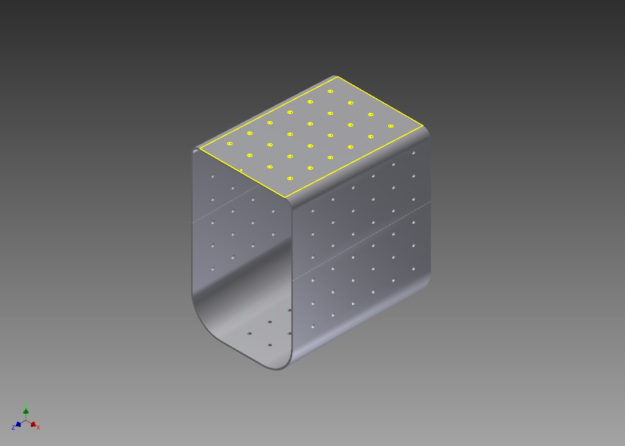
I am new to Inventor. I am trying to flatten a shell. It is pressure vessel component. I can rip it and unfold just fine, but the final part, when built, is too big to mfg in one piece. I noted that multiple rips are supported and I can do two rips fine. I basically have a top half and bottom half. But when I flatten it, one half is missing. I stumbled upon "unfold". I can do that to both halves and have them as flat plates seperated in space in one .ipt. . If I try to create 2D drawings, one half is missing. I can't find it to create projections in a dwg. I've assumed this might work better if I created an assembly of the 2 halves, but haven't been able to erase half as ripped and save as(pt1, pt2), to create the two parts to the assy. Any ideas?
Solved! Go to Solution.
Solved by rsgallo. Go to Solution.
8 REPLIES 8
Message 2 of 9
07-17-2011
03:47 PM
- Mark as New
- Bookmark
- Subscribe
- Mute
- Subscribe to RSS Feed
- Permalink
- Report
07-17-2011
03:47 PM
I would do Derived Components to get the flats.
-----------------------------------------------------------------------------------------
Autodesk Inventor 2019 Certified Professional
Autodesk AutoCAD 2013 Certified Professional
Certified SolidWorks Professional
The CADWhisperer YouTube Channel
Message 3 of 9
07-17-2011
07:43 PM
- Mark as New
- Bookmark
- Subscribe
- Mute
- Subscribe to RSS Feed
- Permalink
- Report
07-17-2011
07:43 PM
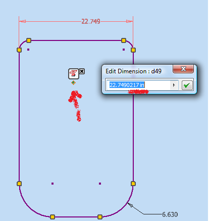
I tried your suggestion. It still treats the model as one part, even though it is ripped into two parts. I could not derive one half from the other. I've included the part file for perusal. Am I missing something?
Thanks,
Message 4 of 9
07-18-2011
02:33 AM
- Mark as New
- Bookmark
- Subscribe
- Mute
- Subscribe to RSS Feed
- Permalink
- Report
07-18-2011
02:33 AM
JD is suggesting tha youuse your origional part as a master part, which will control two derived parts.
Create the split in your master part - being caerful to make sure that you chose the 'New Body' option.
Now use the make components tool to create two derived parts, each containing a reference to your origional master part.
Each of these parts should flattern sucessfully.
Message 5 of 9
07-18-2011
03:29 AM
- Mark as New
- Bookmark
- Subscribe
- Mute
- Subscribe to RSS Feed
- Permalink
- Report
07-18-2011
03:29 AM
please refer to the attachment.
I have just followed the previous 2 peoples instructions.
Message 6 of 9
07-18-2011
03:03 PM
- Mark as New
- Bookmark
- Subscribe
- Mute
- Subscribe to RSS Feed
- Permalink
- Report
07-18-2011
03:03 PM
I gather I should use "split" with the model, instead of "rip" as a sheet metal function. I tried that, but when I attempt to derive parts, or make component, there is still only one solid available and it is the total model.
rageshindi, I cannot open the file you sent back. A dependent file is missing.
Thanks,
Message 7 of 9
07-18-2011
03:44 PM
- Mark as New
- Bookmark
- Subscribe
- Mute
- Subscribe to RSS Feed
- Permalink
- Report
07-18-2011
03:44 PM
Nothing you have done makes sense to me?
I would start over using obvious symmetry about the origin
see http://home.pct.edu/~jmather/skillsusa%20university.pdf
your first sketch isn't constrained and it looks like you are doing too much work
(see attached)
This is a good example of why Inventor Fusion should never have seen the light of day.
-----------------------------------------------------------------------------------------
Autodesk Inventor 2019 Certified Professional
Autodesk AutoCAD 2013 Certified Professional
Certified SolidWorks Professional
The CADWhisperer YouTube Channel
Message 8 of 9
07-20-2011
06:39 PM
- Mark as New
- Bookmark
- Subscribe
- Mute
- Subscribe to RSS Feed
- Permalink
- Report
07-20-2011
06:39 PM
It is true the drawing was cluttered with various trial and error. I need to learn more about drawing constraints.
I had some phone support due me on my upgrade purchase, so I called. Nothing wrong with my file. Yes, it is "spit" in the model space, not "rip" in sheetmetal. After splitting, then one must "manage"> "make component". The halves must be selected to show up in the Make Components window. This is what I was missing. I saw none or one solid and had no idea what to do. Thanks for your help.
Message 9 of 9
07-21-2011
12:51 AM
- Mark as New
- Bookmark
- Subscribe
- Mute
- Subscribe to RSS Feed
- Permalink
- Report
07-21-2011
12:51 AM
In addition to getting the sketches constrained/dimensioned - also take a look at how the holes were placed in the inclined plane (check in derived flat pattern). They are not perpendicular to the face as is.
-----------------------------------------------------------------------------------------
Autodesk Inventor 2019 Certified Professional
Autodesk AutoCAD 2013 Certified Professional
Certified SolidWorks Professional
The CADWhisperer YouTube Channel
Reply
Topic Options
- Subscribe to RSS Feed
- Mark Topic as New
- Mark Topic as Read
- Float this Topic for Current User
- Bookmark
- Subscribe
- Printer Friendly Page
