Community
Inventor Forum
Welcome to Autodesk’s Inventor Forums. Share your knowledge, ask questions, and explore popular Inventor topics.
Turn on suggestions
Auto-suggest helps you quickly narrow down your search results by suggesting possible matches as you type.
Reply
Topic Options
- Subscribe to RSS Feed
- Mark Topic as New
- Mark Topic as Read
- Float this Topic for Current User
- Bookmark
- Subscribe
- Printer Friendly Page
Message 1 of 9
01-16-2013
09:35 AM
- Mark as New
- Bookmark
- Subscribe
- Mute
- Subscribe to RSS Feed
- Permalink
- Report
01-16-2013
09:35 AM
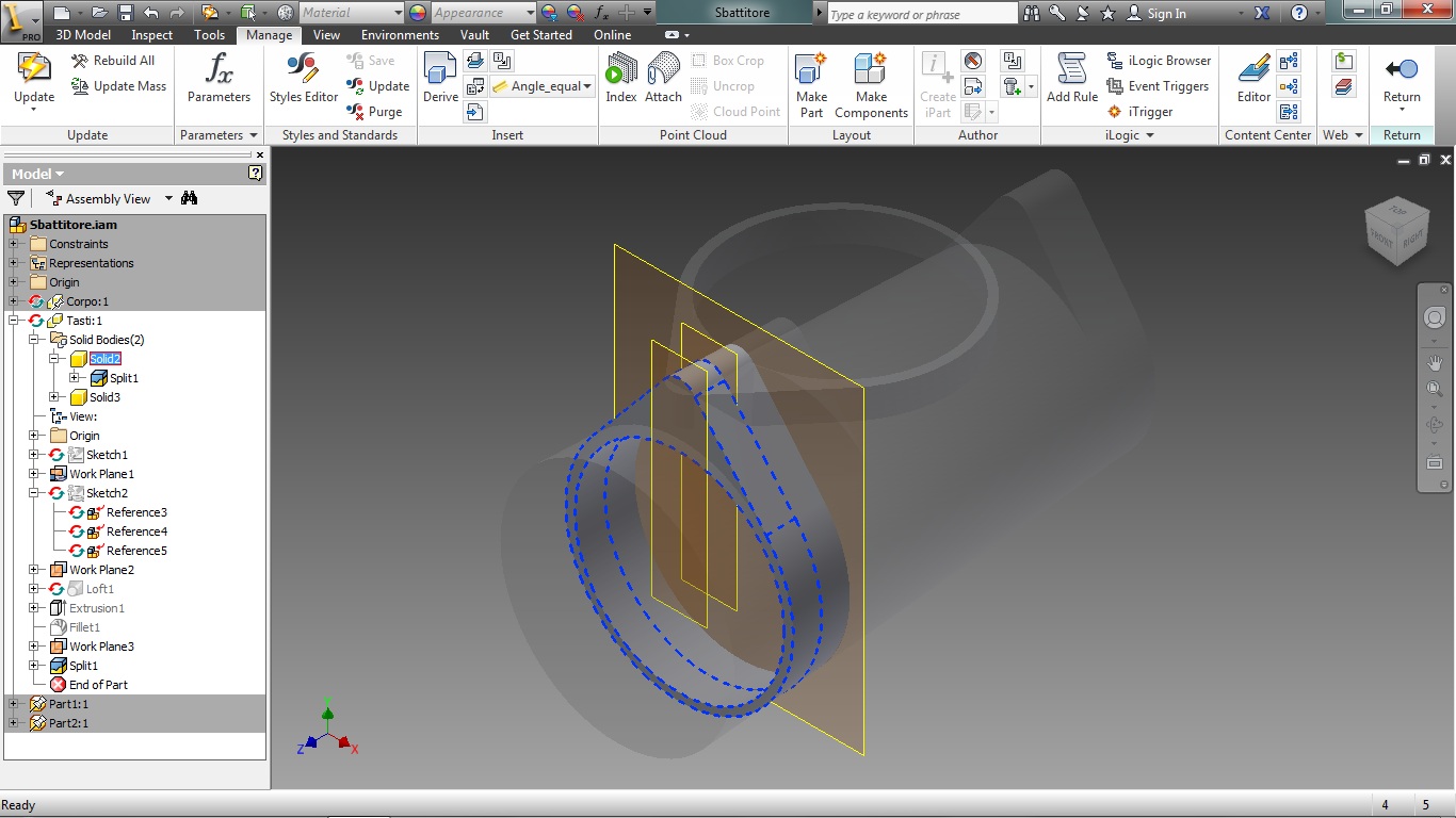
See what happens if i make a part after a split has taken place. This thing is driving me crazy. Misplaced part? How it's possible? How to correct it, or how to prevent it from happening?
Thanks in advance.
Federica
Solved! Go to Solution.
Solved by LT.Rusty. Go to Solution.
8 REPLIES 8
Message 4 of 9
01-16-2013
10:28 AM
- Mark as New
- Bookmark
- Subscribe
- Mute
- Subscribe to RSS Feed
- Permalink
- Report
01-16-2013
10:28 AM
The problem is the orientation of the original part.
If you look at tasti.ipt, you'll notice that when you hit the home button on the view cube, you're set with the Z axis as up and the hole through the part is oriented along the Y axis. When you use Make Part, the new part that's created is oriented in the same fashion, but because the Home View hasn't been modified, the orientation looks a little strange.
Basically, the program is working exactly the way it's supposed to.
Rusty
Message 5 of 9
01-16-2013
10:49 AM
- Mark as New
- Bookmark
- Subscribe
- Mute
- Subscribe to RSS Feed
- Permalink
- Report
01-16-2013
10:49 AM
The y anz axes switch when when i click make part. Can i solve it with a mirror?
How can i make it stand where i need it? Something like an in place cut.
Message 6 of 9
01-16-2013
11:00 AM
- Mark as New
- Bookmark
- Subscribe
- Mute
- Subscribe to RSS Feed
- Permalink
- Report
01-16-2013
11:00 AM
No, a mirror isn't going to fix it.
The axes haven't changed at all, only the relationship between the axes and the view cube's "home"
orientation has changed between your original part and your derived part. The UCS that you're seeing in your assembly is that of the assembly, not the part.


Rusty
Message 8 of 9
01-16-2013
11:30 AM
- Mark as New
- Bookmark
- Subscribe
- Mute
- Subscribe to RSS Feed
- Permalink
- Report
01-16-2013
11:30 AM
There's a few solutions.
1. Make sure you model all your parts with the same "up" orientation. In this case if you wanted the flange-thingy to face "up" and the axis of the hole to be on the Z-axis, it would have been easiest to model it in that orientation in the first place.
2. In the derived part, use MOVE BODY to force the alignment you want.
3. In the assembly, just use constraints to put the part where you want it to go. That's probably the easiest course for you to take at this stage, unless you feel like re-modeling the part.
I use #3 constantly, because for some reason my boss uses Z as "up" where everyone else uses "Y." I have to re-align his parts constantly for insertion in my assemblies.
Rusty
Message 9 of 9
01-16-2013
11:44 AM
- Mark as New
- Bookmark
- Subscribe
- Mute
- Subscribe to RSS Feed
- Permalink
- Report
01-16-2013
11:44 AM
Really thanks Rusty for helping me getting out of this trouble. I used the option number 3 and i well assembled the parts together.
Reply
Topic Options
- Subscribe to RSS Feed
- Mark Topic as New
- Mark Topic as Read
- Float this Topic for Current User
- Bookmark
- Subscribe
- Printer Friendly Page
