Community
Inventor Forum
Welcome to Autodesk’s Inventor Forums. Share your knowledge, ask questions, and explore popular Inventor topics.
Turn on suggestions
Auto-suggest helps you quickly narrow down your search results by suggesting possible matches as you type.
Reply
Topic Options
- Subscribe to RSS Feed
- Mark Topic as New
- Mark Topic as Read
- Float this Topic for Current User
- Bookmark
- Subscribe
- Printer Friendly Page
Message 1 of 8
Anonymous
651 Views, 7 Replies
09-24-2013
05:16 AM
- Mark as New
- Bookmark
- Subscribe
- Mute
- Subscribe to RSS Feed
- Permalink
- Report
09-24-2013
05:16 AM
Geometric Tol. question
Basic question but could lead me in the right direction from here...
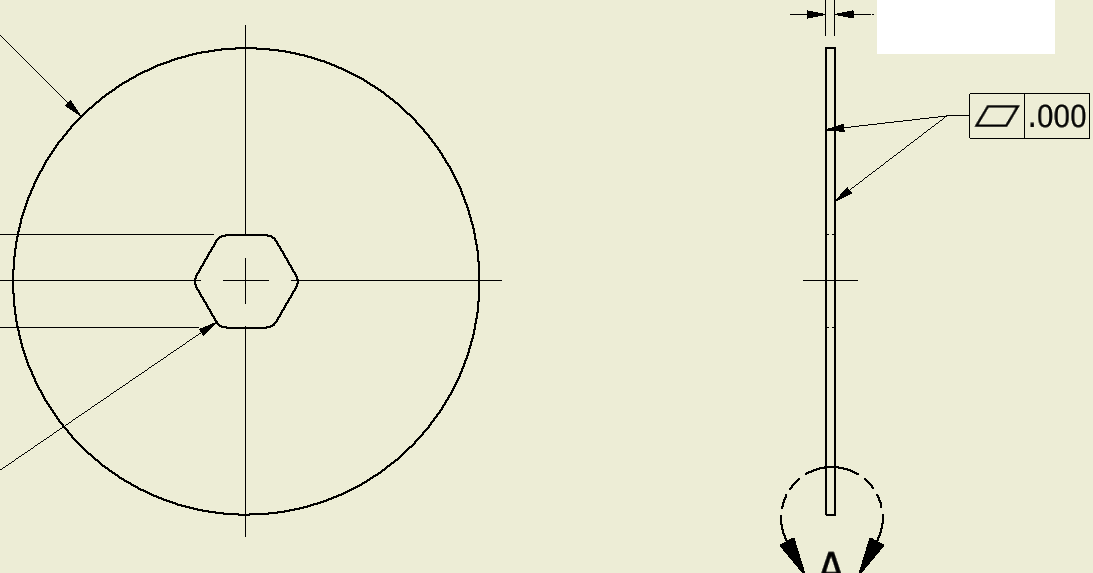
I have a drawing(OLD) that says "Sides must be flat up to Diameter" Where te arrows are pointed are where the note was. From what I know can geometric tolerances be used instead of that note. If so I did some work seeing how to replicate it with that and this is what I did. Does that make sense and if maybe there are more resources out there to get me on my way if I run into more stuff like this.
7 REPLIES 7
Message 2 of 8
09-24-2013
05:28 AM
- Mark as New
- Bookmark
- Subscribe
- Mute
- Subscribe to RSS Feed
- Permalink
- Report
09-24-2013
05:28 AM
Be very careful with GD&T.. Trying to be "too fancy" can just raise the cost of your parts considerably.
In my opinion its better to not use GD&T if you don't know exactly how it works.
google "gd&t"
-------------------------------------------------------------------------------------------
Inventor 2023 - Dell Precision 5570
Did you find this reply helpful ? If so please use the Accept Solution button below.
Maybe buy me a beer through Venmo @mcgyvr1269
Message 3 of 8
09-24-2013
05:42 AM
- Mark as New
- Bookmark
- Subscribe
- Mute
- Subscribe to RSS Feed
- Permalink
- Report
09-24-2013
05:42 AM
Thats like syaing don't get married when your married for 50 years :). I worked at a few places but never was in a situation yet to use it round the clock ro even for a few minutes. I guess some companies love it and some don't and some don't even know. I probably was in the "Don't even know" category.
Message 4 of 8
09-24-2013
06:36 AM
- Mark as New
- Bookmark
- Subscribe
- Mute
- Subscribe to RSS Feed
- Permalink
- Report
09-24-2013
06:36 AM
Not knowing design intent it's difficult to say. But a .000 tolerance is not realistic, I assume this was just for demonstration purposes.
Again, working from ignorance, I'd probably use flat for one side and parallel for the other.
PDSU 2016
Message 5 of 8
09-24-2013
07:44 AM
- Mark as New
- Bookmark
- Subscribe
- Mute
- Subscribe to RSS Feed
- Permalink
- Report
09-24-2013
07:44 AM
GD&T is all about expressing design intent. Without knowing what you want to say, how can we tell you how to say it?
Mike (not Matt) Rattray

Message 7 of 8
Anonymous
in reply to:
Anonymous
09-24-2013
08:21 AM
- Mark as New
- Bookmark
- Subscribe
- Mute
- Subscribe to RSS Feed
- Permalink
- Report
09-24-2013
08:21 AM
Hi Jbelle7435,
As all above have correctly stated, the cost of your part could rocket if
GD&T is used unnecessary and it would be wrong to give you an answer
as to how tight your tolerance should be.
With that caveat mind, here is an example of how I would approach
a flatness tol on one side and a parallel tol on the other to tie them together.
Again this is only a suggested guild, your actual tol / price requirement may be very different.
Hope this is of help
Cheers
Mark
Inventor 2013

Message 8 of 8
Anonymous
in reply to:
Anonymous
09-24-2013
08:32 AM
- Mark as New
- Bookmark
- Subscribe
- Mute
- Subscribe to RSS Feed
- Permalink
- Report
09-24-2013
08:32 AM
Thanks that is really nice and maybe what I even wanted except right now this is a new language that can't learn in 1 day and a shop floor would have to learn as well. I will def save this as a good example!
Reply
Topic Options
- Subscribe to RSS Feed
- Mark Topic as New
- Mark Topic as Read
- Float this Topic for Current User
- Bookmark
- Subscribe
- Printer Friendly Page
Forums Links
Can't find what you're looking for? Ask the community or share your knowledge.
Post to forums
