Community
Inventor Forum
Welcome to Autodesk’s Inventor Forums. Share your knowledge, ask questions, and explore popular Inventor topics.
Turn on suggestions
Auto-suggest helps you quickly narrow down your search results by suggesting possible matches as you type.
Reply
Topic Options
- Subscribe to RSS Feed
- Mark Topic as New
- Mark Topic as Read
- Float this Topic for Current User
- Bookmark
- Subscribe
- Printer Friendly Page
Message 1 of 41
12-28-2010
01:32 PM
- Mark as New
- Bookmark
- Subscribe
- Mute
- Subscribe to RSS Feed
- Permalink
- Report
12-28-2010
01:32 PM
Hello,
Can we do a Feature driven pattern in Inventor?
I dont have any parts to share, but can explain my requirement.
I have a assembly file consisting of couple of parts. One of the part is rectangular plate with a several square holes. These In the part level these Sq holes are created using a rectangular pattern.
At the assemb;y level, I want to insert a square plug (plastic Cover) that closes these square holes. I need to know if we can link this pattern to the Original rectangular pattern at the part level.
I have used this kind of feature in solidoworks & its called as Feature Driven Pattern. I need to know if this is possible here.
If so, It makes it so easy to install these covers to all the holes. & when the original hole pattern changes, the cover pattern automatically updates at the assembly level.
Thanks
C1
Inventor Professional 2020
Vault Professional 2020
AutoCAD 2020
Inventor Professional 2020
Vault Professional 2020
AutoCAD 2020
Solved! Go to Solution.
40 REPLIES 40
Message 21 of 41
09-12-2013
08:26 AM
- Mark as New
- Bookmark
- Subscribe
- Mute
- Subscribe to RSS Feed
- Permalink
- Report
09-12-2013
08:26 AM
Attach your assembly here.
Both of those videos are fairly easy to do (in Inventor).
But I don't have time to model the parts for you.
-----------------------------------------------------------------------------------------
Autodesk Inventor 2019 Certified Professional
Autodesk AutoCAD 2013 Certified Professional
Certified SolidWorks Professional
Message 22 of 41
09-12-2013
09:48 AM
- Mark as New
- Bookmark
- Subscribe
- Mute
- Subscribe to RSS Feed
- Permalink
- Report
09-12-2013
09:48 AM
Did this quick example while waiting for your assembly (attach your SWx assembly here if you don't know how to use Inventor - I can use SWx too).

-----------------------------------------------------------------------------------------
Autodesk Inventor 2019 Certified Professional
Autodesk AutoCAD 2013 Certified Professional
Certified SolidWorks Professional
Message 23 of 41
09-12-2013
11:32 AM
- Mark as New
- Bookmark
- Subscribe
- Mute
- Subscribe to RSS Feed
- Permalink
- Report
09-12-2013
11:32 AM
I am able to do the same thing using "Bolted connection component generator". but can you do the same thing using any other part other than fasteners? Can you distribute a part that I created earlier?
I can't attach pieces here due to companiy's policy. But I will attach something similar soon.
Message 24 of 41
09-12-2013
11:42 AM
- Mark as New
- Bookmark
- Subscribe
- Mute
- Subscribe to RSS Feed
- Permalink
- Report
09-12-2013
11:42 AM
@Anonymous wrote:
I am able to do the same thing using "Bolted connection component generator". but can you do the same thing using any other part other than fasteners? Can you distribute a part that I created earlier?
I can't attach pieces here due to companiy's policy. But I will attach something similar soon.
I didn't use the Bolted Connection generator. (that topic was already covered earlier in this thread) The component patttern would work with virtually any component.
While I was waiting for you to attach a dummy assembly that exhibits all the behavior of what you want to see in your proprietary assembly - so I created one from scratch myself. I did not use any of the Design Accelerators (like Frame Generator) to show that it can be done with any component.

I have two legs in this assembly - note Instance #2 of the component Leg is highlited.
I did a Component Pattern of each leg to follow the rails.
-----------------------------------------------------------------------------------------
Autodesk Inventor 2019 Certified Professional
Autodesk AutoCAD 2013 Certified Professional
Certified SolidWorks Professional
Message 25 of 41
Anonymous
in reply to:
Anonymous
09-12-2013
12:09 PM
- Mark as New
- Bookmark
- Subscribe
- Mute
- Subscribe to RSS Feed
- Permalink
- Report
09-12-2013
12:09 PM
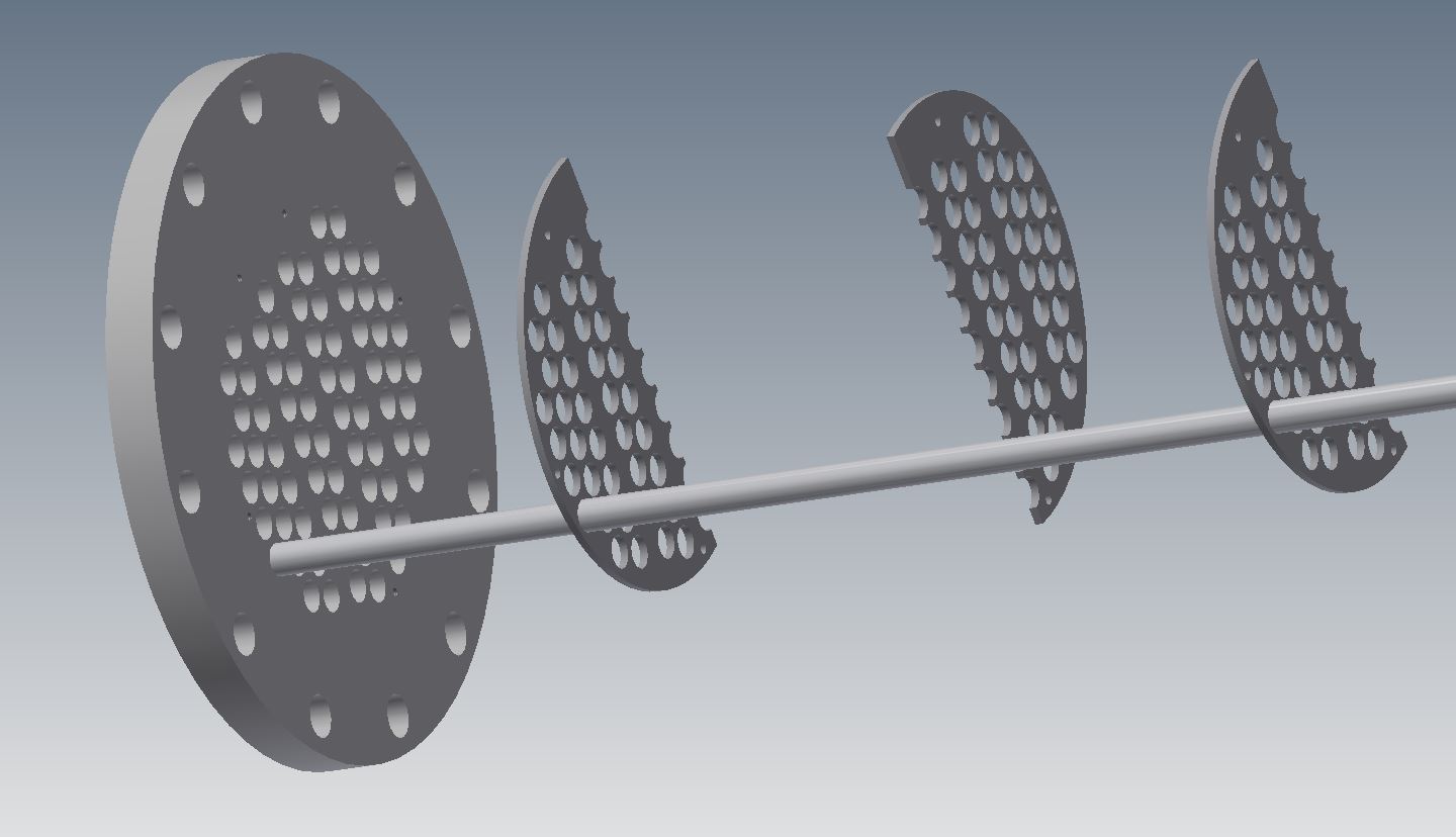
This is my project in which I want to distrubute the rod into each hole by one command. As you can see the distances between holes are not the same. Please tell me if this is possbile in inventor. I know this is very easy in solidworks. Please do not recommend me rectangular and circular pattern. i have already tried.
Message 27 of 41
09-13-2013
07:18 AM
- Mark as New
- Bookmark
- Subscribe
- Mute
- Subscribe to RSS Feed
- Permalink
- Report
09-13-2013
07:18 AM
http://screencast.com/t/OJlXsxralIa
C1
Inventor Professional 2020
Vault Professional 2020
AutoCAD 2020
Inventor Professional 2020
Vault Professional 2020
AutoCAD 2020
Message 28 of 41
09-13-2013
07:56 AM
- Mark as New
- Bookmark
- Subscribe
- Mute
- Subscribe to RSS Feed
- Permalink
- Report
09-13-2013
07:56 AM
CAD-One
You left out a critical step in your video.
For some reason yours still worked, but I didn't see you set the Direction 1 Orientation.
Also, I often set the seed for my pattern as a different color so that I don't have to go back and identify it.
-----------------------------------------------------------------------------------------
Autodesk Inventor 2019 Certified Professional
Autodesk AutoCAD 2013 Certified Professional
Certified SolidWorks Professional
Message 29 of 41
09-13-2013
08:58 AM
- Mark as New
- Bookmark
- Subscribe
- Mute
- Subscribe to RSS Feed
- Permalink
- Report
09-13-2013
08:58 AM
Thanks JD.
Thats correct. Guys this what I missed out. This would have controlled the orientation od the screw.

C1
Inventor Professional 2020
Vault Professional 2020
AutoCAD 2020
Inventor Professional 2020
Vault Professional 2020
AutoCAD 2020
Message 31 of 41
Anonymous
in reply to:
Anonymous
09-13-2013
09:36 AM
- Mark as New
- Bookmark
- Subscribe
- Mute
- Subscribe to RSS Feed
- Permalink
- Report
09-13-2013
09:36 AM
however after retrying we were not able to achieve our goal as Inventor wasnt able to recognize INSERTION POINTS. We are able to make holes in part with insertion points. but when we tried to pattern the rod in assembly it just does not recognize the insertion points or holes feature. Or we miss something. Is it possible to insert (distribute) a part by predefined points (exp. from excel) or sketch?
Attached is the example that we want to achived. Please try to pattern (distribute) the rod into holes by one command
Message 32 of 41
09-13-2013
09:51 AM
- Mark as New
- Bookmark
- Subscribe
- Mute
- Subscribe to RSS Feed
- Permalink
- Report
09-13-2013
09:51 AM
In order for an assembly pattern to recognise an array of features, you must make that array with the feature pattern tool in the part file. When you do that, constrain the object that you want to pattern in the assembly to the base feature of your pattern. JDMather's idea of changing the color of the base feature is very helpful.
If you are trying to make a single sketch with an array of centerpoints, the assembly pattern tool will not "see" that array. Even if you use a sketch pattern to create the array of centerpoints, the assembly pattern tool will not "see" that array. You will have to constrain each component individually. This is the main reason that I avoid placing more than one centerpoint in a sketch that locates a hole.
If you create an ipart factory with a pattern feature and you place a member in an assembly, the assembly pattern tool will not "see" that array in any of the members. The derive operation that creates members from the factory hides the pattern feature.
Do note that you can pattern patterns in parts and assemblies.
Steve Walton
Did you find this post helpful? Feel free to Like this post.
Did your question get successfully answered? Then click on the ACCEPT SOLUTION button.
Inventor 2023
Vault Professional 2023
Message 33 of 41
09-13-2013
10:36 AM
- Mark as New
- Bookmark
- Subscribe
- Mute
- Subscribe to RSS Feed
- Permalink
- Report
09-13-2013
10:36 AM
Can you attach a real assembly - I would not consider this good modeling practice in Inventor or SolidWorks.
You should be able to make something up that exhibits all the behavior of your proprietary work without giving anything away. (I could do it myself from looking at your previous screen capture, but -.....)
http://usa.autodesk.com/adsk/servlet/ps/dl/item?siteID=123112&id=21702054&linkID=9242019
-----------------------------------------------------------------------------------------
Autodesk Inventor 2019 Certified Professional
Autodesk AutoCAD 2013 Certified Professional
Certified SolidWorks Professional
Message 34 of 41
09-13-2013
11:24 AM
- Mark as New
- Bookmark
- Subscribe
- Mute
- Subscribe to RSS Feed
- Permalink
- Report
09-13-2013
11:24 AM
JD. it s simple. just distribute the rods inside each holes by pattern. Do it anyway you like. it's so clear what I need. You know that is very easy in Solidworks. i am getting feeling that is just NOT possible in Inventor. We work with heat exchangers that requires lots of tubes (which i call rods here) inside a container. Thus, we do not want to insert each tube one by one which will take lots of time and effort to control.
Message 35 of 41
Anonymous
in reply to:
Anonymous
09-13-2013
11:31 AM
- Mark as New
- Bookmark
- Subscribe
- Mute
- Subscribe to RSS Feed
- Permalink
- Report
09-13-2013
11:31 AM
Since I am about to cross out feature pattern option by center point, Would anyone recommend me to achieve this by a trick through " Bolted Connection Component Generator"? Perhaps somehow insert (or save) my tube (rod) as a Fasterner inside BCCG and then distribute (pattern) it as fastener?
Message 36 of 41
09-15-2013
09:30 PM
- Mark as New
- Bookmark
- Subscribe
- Mute
- Subscribe to RSS Feed
- Permalink
- Report
09-15-2013
09:30 PM
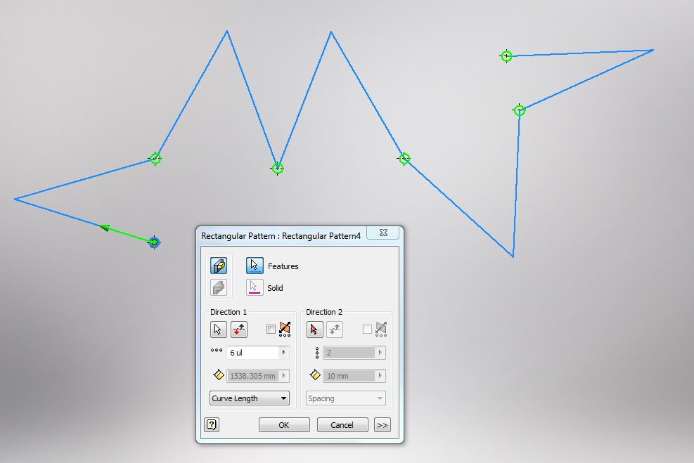
Seytafun,
I have come from an SW environment & always used sketch based pattern but as we all know, Inventor lacks such a feature. I came up with a work around which gives you point locations at varying spacing aligned or any point required.
See this thread I posted earlier:
http://forums.autodesk.com/t5/forums/recentpostspage/post-type/message/user-id/1693791
This works if points are not alligned also - just ensure the zig-zag curve does not cross over itself.
See attached Image.
Hope this helps - it has certainly helped in my application.
Message 37 of 41
09-17-2013
11:28 AM
- Mark as New
- Bookmark
- Subscribe
- Mute
- Subscribe to RSS Feed
- Permalink
- Report
09-17-2013
11:28 AM
Thank you very much forbillian. I have tried your method and yes it works. However drawing equal curve lines between at least 50 points is a challenge and sometimes impossible as some locations are too close to each other. So we are locating tubes by small patterns or individually for now.
Message 38 of 41
09-27-2013
07:38 AM
- Mark as New
- Bookmark
- Subscribe
- Mute
- Subscribe to RSS Feed
- Permalink
- Report
09-27-2013
07:38 AM
I am an imigrant from SolidWorks. In SW you can insert a part or assembly on a hole, then using the "Feature Driven Pattern" command, you can have that component repeat on all of the same holes made in a single hole feature operation, just by picking any of those holes. These holes were made with a traditional sketch that is dimensioned according to your needs. For example if you have a plate that has 4 mounting holes, all are 1/2" from the edges because that's the way the sketch is done. This means that if you change the size of the plate, the holes change with it and are always 1/2 from the edge. It appears that the only way to use Inventor's "Pattern" for the inserted component is to pick a "patterned" set of holes. Well, this makes absolutely no sense from a design standpoint, because placing one hole then patterning it, totally loses the parametric aspect of editing. If I change the size of the plate, the pattern does not automatically change. This means I would have to go an extra step and change the holes' pattern. (senseless).
Am I missing something. I discovered that a Content Center item when placed can be chosen to do all holes at the time of the placement only.( I'm gonna take this opportunity to say that I have found it takes about 3 times as many mouse clicks to do same thing in SW)
Message 39 of 41
10-17-2014
04:41 AM
- Mark as New
- Bookmark
- Subscribe
- Mute
- Subscribe to RSS Feed
- Permalink
- Report
10-17-2014
04:41 AM
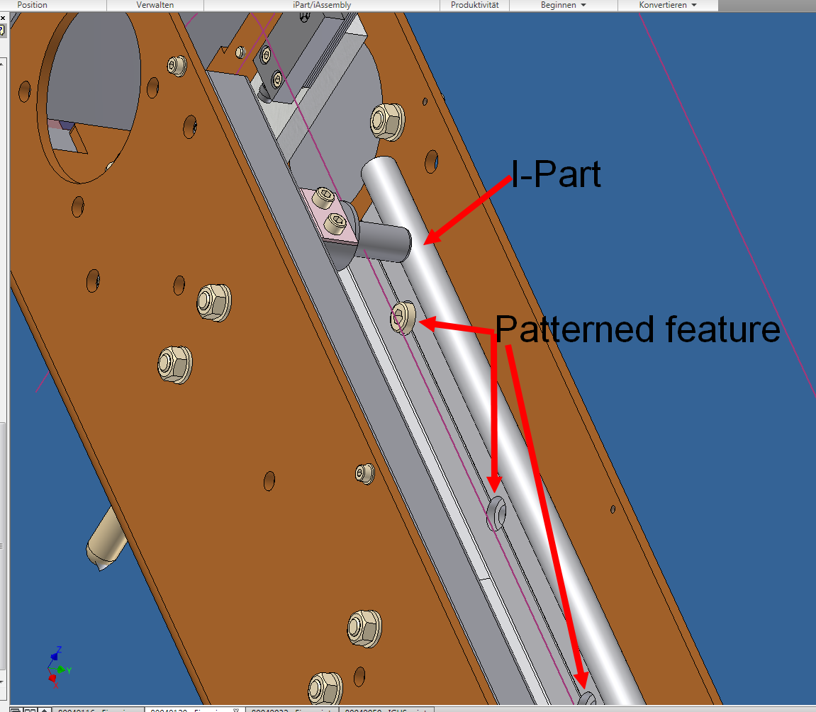
Hi,
you wrote:"If you create an ipart factory with a pattern feature and you place a member in an assembly, the assembly pattern tool will not "see" that array in any of the members. The derive operation that creates members from the factory hides the pattern feature. "
This addresses exactly what I tried to achieve because I still think „SolidWorks configurations“. Please find the attached picture.
Is there a workaround to utilise associative component patterns within an assembly containing ipart members?
Kind regards
Message 40 of 41
10-17-2014
07:13 AM
- Mark as New
- Bookmark
- Subscribe
- Mute
- Subscribe to RSS Feed
- Permalink
- Report
10-17-2014
07:13 AM
The derive operation that Inventor uses to create the ipart member from the ipart factory destroys the feature pattern information that the assembly component pattern tool needs.
I think there is a workaround that you can use. You will need to export the dimension parameters that drive the feature pattern in the ipart to the assembly. Once those dimensions are available in the assembly, create a pattern and use them to drive the count and offset dimensions of the components.
See:
http://help.autodesk.com/view/INVNTOR/2014/ENU/?guid=GUID-7F5F3C96-5A17-405A-8D2B-FD46E488FDFB
for some information about how to link parameters between models. I don't have an example that I can post, so you will have to experiment to get it to work.
Steve Walton
Did you find this post helpful? Feel free to Like this post.
Did your question get successfully answered? Then click on the ACCEPT SOLUTION button.
Inventor 2023
Vault Professional 2023
Reply
Topic Options
- Subscribe to RSS Feed
- Mark Topic as New
- Mark Topic as Read
- Float this Topic for Current User
- Bookmark
- Subscribe
- Printer Friendly Page
Forums Links
Can't find what you're looking for? Ask the community or share your knowledge.
Post to forums
