Community
Inventor Forum
Welcome to Autodesk’s Inventor Forums. Share your knowledge, ask questions, and explore popular Inventor topics.
Turn on suggestions
Auto-suggest helps you quickly narrow down your search results by suggesting possible matches as you type.
Reply
Topic Options
- Subscribe to RSS Feed
- Mark Topic as New
- Mark Topic as Read
- Float this Topic for Current User
- Bookmark
- Subscribe
- Printer Friendly Page
Message 1 of 2
Anonymous
1097 Views, 1 Reply
04-28-2012
09:12 AM
- Mark as New
- Bookmark
- Subscribe
- Mute
- Subscribe to RSS Feed
- Permalink
- Report
04-28-2012
09:12 AM
Disc cam with a modified sine probile
I need to generate a disc cam with a modified sine profile but there is no motion function of that name in the Disc Cam Component Generator. Does anyone knows how to generate a modified sine disc cam?
1 REPLY 1
Message 2 of 2
04-30-2012
12:43 PM
- Mark as New
- Bookmark
- Subscribe
- Mute
- Subscribe to RSS Feed
- Permalink
- Report
04-30-2012
12:43 PM
You can use Dynamic Simulation and the "Export trace to Sketch" functionality as the sweep path.
The basic workflow (for a cylindrical cam, but it should be very similar for a disc cam):
1) Create the cam (no groove cut) and follower assembly (with follower sketch profile)
2) In Dynamic Simulation allow or create the cylindrical joint
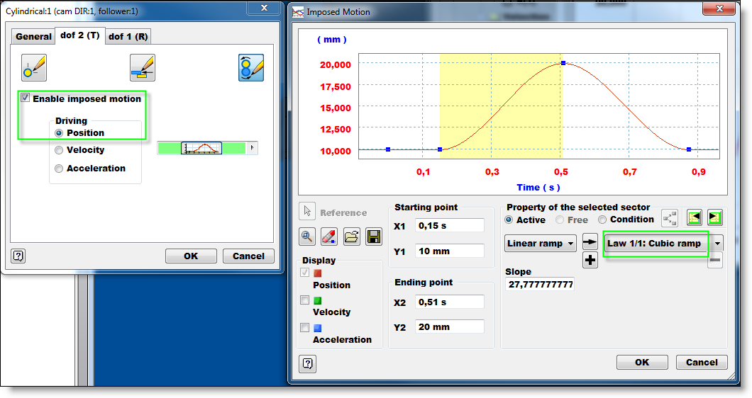
3) Use the imposed motion to create the desired movement using a sinusoidal equation
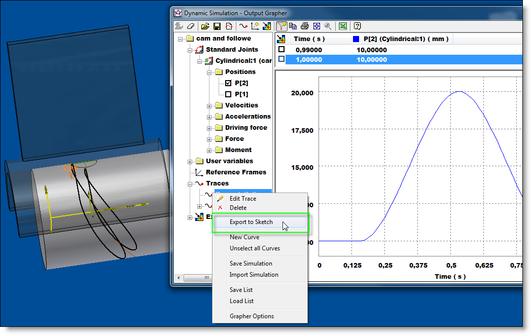
4) Add traces (one at the profile center, and one at the profile "corner" to be used as the sweep rail)
5) Export the trace to sketch and choose the cam part
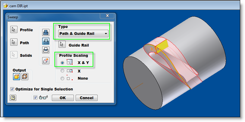
6) Using the Exported traces (they will be 3D sketch splines) and the follower sketch profile, cut the cam groove
The really beneficial part about incorperating DS is that you can run the simulation using a 3D contact to ensure there isn't any penetration or "chatter" between the cam groove and follower "lobe".
This is the best way I know how to model a cam groove in Inventor. However, using a 2D profile to cut the 3D groove is not the same as using a 3D body to cut the groove. It has it's limitations...
Hope this helps, -Hugh
Thanks, -Hugh
[Edit: couldn't squeeze in the final image as an attachment]

Hugh Henderson
QA Engineer (Fusion Simulation)
Reply
Topic Options
- Subscribe to RSS Feed
- Mark Topic as New
- Mark Topic as Read
- Float this Topic for Current User
- Bookmark
- Subscribe
- Printer Friendly Page
Forums Links
Can't find what you're looking for? Ask the community or share your knowledge.
Post to forums
