Community
Inventor Forum
Welcome to Autodesk’s Inventor Forums. Share your knowledge, ask questions, and explore popular Inventor topics.
Turn on suggestions
Auto-suggest helps you quickly narrow down your search results by suggesting possible matches as you type.
Reply
Topic Options
- Subscribe to RSS Feed
- Mark Topic as New
- Mark Topic as Read
- Float this Topic for Current User
- Bookmark
- Subscribe
- Printer Friendly Page
Message 1 of 17
09-20-2012
07:03 AM
- Mark as New
- Bookmark
- Subscribe
- Mute
- Subscribe to RSS Feed
- Permalink
- Report
09-20-2012
07:03 AM
I have a problem when I want to use a cutout.
My purpose is to get a perforated plate but Inventor doesn't show this.
Only the black color is shown and not the holes.
What am I doing wrong?
Thanks in advance
Nick
Solved! Go to Solution.
Solved by nick.jeuris. Go to Solution.
16 REPLIES 16
Message 2 of 17
09-20-2012
07:09 AM
- Mark as New
- Bookmark
- Subscribe
- Mute
- Subscribe to RSS Feed
- Permalink
- Report
09-20-2012
07:09 AM
Make sure the "cut" is selected in the command dialog window.
I can't open your file because I am still on 2012.

Best Regards,
Scott McFadden
(Colossians 3:23-25)
Scott McFadden
(Colossians 3:23-25)
Message 3 of 17
09-20-2012
07:26 AM
- Mark as New
- Bookmark
- Subscribe
- Mute
- Subscribe to RSS Feed
- Permalink
- Report
09-20-2012
07:26 AM
if you're just using that .png file to similate perforated plate, the cut away won't work.
Message 4 of 17
09-20-2012
07:30 AM
- Mark as New
- Bookmark
- Subscribe
- Mute
- Subscribe to RSS Feed
- Permalink
- Report
09-20-2012
07:30 AM
Hi Cadmanto
I'm not doing an extrude, but I am using the cutout option in the appearance menu.
See the screenshot in attachment.
Nick
Message 5 of 17
09-20-2012
07:32 AM
- Mark as New
- Bookmark
- Subscribe
- Mute
- Subscribe to RSS Feed
- Permalink
- Report
Message 6 of 17
09-20-2012
07:55 AM
- Mark as New
- Bookmark
- Subscribe
- Mute
- Subscribe to RSS Feed
- Permalink
- Report
09-20-2012
07:55 AM
I'm not sure what you did wrong, but after I cleard your overrides and set generic to use your image file it worked fine.

Mike (not Matt) Rattray

Message 7 of 17
09-20-2012
07:59 AM
- Mark as New
- Bookmark
- Subscribe
- Mute
- Subscribe to RSS Feed
- Permalink
- Report
09-20-2012
07:59 AM
Sorry I misunderstood your issue.
2 thoughts, first maybe the transparency needs to be adjusted on the png file
and second, can you use this appearance in the color portion of the style and standard editor?

Best Regards,
Scott McFadden
(Colossians 3:23-25)
Scott McFadden
(Colossians 3:23-25)
Message 8 of 17
09-20-2012
08:01 AM
- Mark as New
- Bookmark
- Subscribe
- Mute
- Subscribe to RSS Feed
- Permalink
- Report
09-20-2012
08:01 AM
You forgot that there are no longer colors in 2013. He has to work with the appearance editor.
Mike (not Matt) Rattray
Message 9 of 17
09-20-2012
08:06 AM
- Mark as New
- Bookmark
- Subscribe
- Mute
- Subscribe to RSS Feed
- Permalink
- Report
09-20-2012
08:06 AM
@Cadmanto wrote:Sorry I misunderstood your issue.
..... Styles and Standards, Materials and Colors questions based on 2012 and earlier releases.
It has all changed in 2013.
-----------------------------------------------------------------------------------------
Autodesk Inventor 2019 Certified Professional
Autodesk AutoCAD 2013 Certified Professional
Certified SolidWorks Professional
Message 10 of 17
09-20-2012
09:20 AM
- Mark as New
- Bookmark
- Subscribe
- Mute
- Subscribe to RSS Feed
- Permalink
- Report
09-20-2012
09:20 AM
Alrighty then...![]()
I am still on 2012, so I guess I have something to look into.
Thanks for the heads up guys.
Best Regards,
Scott McFadden
(Colossians 3:23-25)
Scott McFadden
(Colossians 3:23-25)
Message 11 of 17
09-20-2012
01:31 PM
- Mark as New
- Bookmark
- Subscribe
- Mute
- Subscribe to RSS Feed
- Permalink
- Report
09-20-2012
01:31 PM
nothings wrong with the png file, it's me who misunderstood your question.
I assumed you were doing a view in an idw and while it's been yrs since I had to detail something where I used a perforated sheet metal image, I recall back then there were some things that didn't work right or something or another.
Time for me to sit back and take it all in since I'm 2 versions behind.
Sorry for the confusion!
Message 12 of 17
09-20-2012
11:13 PM
- Mark as New
- Bookmark
- Subscribe
- Mute
- Subscribe to RSS Feed
- Permalink
- Report
09-20-2012
11:13 PM
Hi Mike
I can use the image file as an image but I can't use it as a cutout image.
And I need the holes to be transparant so this isn't a solution for me.
Nick
Message 13 of 17
09-20-2012
11:32 PM
- Mark as New
- Bookmark
- Subscribe
- Mute
- Subscribe to RSS Feed
- Permalink
- Report
09-20-2012
11:32 PM
I have found a solution. Instead of using the png-file to cut out the black circles, I made those circles transparant and used the image as image. Inventor makes transparant what is transparant in the image
Nick
Message 14 of 17
10-30-2012
02:50 PM
- Mark as New
- Bookmark
- Subscribe
- Mute
- Subscribe to RSS Feed
- Permalink
- Report
10-30-2012
02:50 PM
Hi,
This is actually a very important point that appears to be undocumented.
Reading through the wiki help, it will say that shaded modes will not make use of the custom "cutout" image. If you strictly use realistic visual style you will be OK in creating your custom image file and its corresponding cutouts image in photoshop.
The problem comes when you would like to create a custom material (with some transparency) that you need to be displayed correctly in the shaded views on a drawing or in your assembly environment. You will then need to create a png file with transparency in photoshop and use that as Nick has stated.
To summarize, if you use all the visual styles and you create any custom materials/appearances (like expanded metal), you must create a png file with transparency as well as a cutout image and place both into the appearance editor.
Rob
Message 15 of 17
03-06-2013
06:38 AM
- Mark as New
- Bookmark
- Subscribe
- Mute
- Subscribe to RSS Feed
- Permalink
- Report
03-06-2013
06:38 AM
thanks Rob & Nick you have found the missing piece of the puzzle!
i was just working on one of my own appearances tonight and it was behaving a bit randomly until i used your concept.
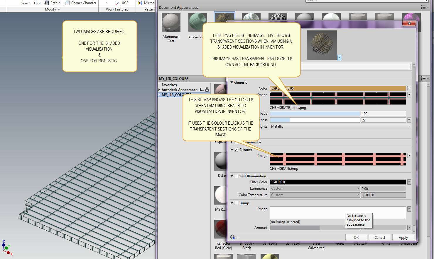
i have attached a snapshot of my appearance which works fine in shaded mode & in realistic mode. as you say there is no mention of this in the documentation. i just read through the help and it would appear to be lacking in a few areas.
ps- the only thing i have not figured out is why my old mesh bitmap file still is able to display transparent sections when i use it for the image. it is still able to show up in inventors shaded visualisation just like it always has in pre 2013 versions.
i recall maybe that in earlier versions, inventor used a method that was based upon whatever the pixel colour in the lower right corner of the image was. if it sees that same colour pixel elsewhere it makes every occurence of it transparent when is maps it into inventor.
for testing, even when i copy my old mesh image it to make a new pattern, i cannot get the copied file to work at all.
thankfully my cheap little snagit software is able to give me transparent backgrounds where i need it to.
thanks again.
best regards,
- Mark
(Kudo or Tag if helpful - in case it also helps others)
PDSU 2020 Windows 10, 64bit.

- Mark
(Kudo or Tag if helpful - in case it also helps others)
PDSU 2020 Windows 10, 64bit.
Message 16 of 17
03-06-2013
07:30 AM
- Mark as New
- Bookmark
- Subscribe
- Mute
- Subscribe to RSS Feed
- Permalink
- Report
03-06-2013
07:30 AM
re following on from my ps above, for getting the the old pre 2013 transparent image sections to work, i remember that if you want the transparent pixel method to work then the file needs to have a symbol as part of the file name, namely the & symbol as the very last character berore the .png or .bmp
eg
MeshScreen&.png
best regards,
- Mark
(Kudo or Tag if helpful - in case it also helps others)
PDSU 2020 Windows 10, 64bit.
- Mark
(Kudo or Tag if helpful - in case it also helps others)
PDSU 2020 Windows 10, 64bit.
Message 17 of 17
03-03-2016
08:44 AM
- Mark as New
- Bookmark
- Subscribe
- Mute
- Subscribe to RSS Feed
- Permalink
- Report
03-03-2016
08:44 AM
Hi All,
I was able to fix my own issue with the cutouts by selecting the object I had my custom material and changing the Materials Mapping setting to planar. Of course, I was doing a planar object. I had a material image from the ACAD Library and my cutout image (in JPG). When it rendered previously, it showed as a bunch of vertical lines, but after I adjusted the Materials Mapping projection setting to Planar, it cleaned right up. The cutout isn't shown in the model space view though, which I'm fine with.
Thanks,
David
Reply
Topic Options
- Subscribe to RSS Feed
- Mark Topic as New
- Mark Topic as Read
- Float this Topic for Current User
- Bookmark
- Subscribe
- Printer Friendly Page
Forums Links
Can't find what you're looking for? Ask the community or share your knowledge.
Post to forums
