Community
Inventor Forum
Welcome to Autodesk’s Inventor Forums. Share your knowledge, ask questions, and explore popular Inventor topics.
Turn on suggestions
Auto-suggest helps you quickly narrow down your search results by suggesting possible matches as you type.
Reply
Topic Options
- Subscribe to RSS Feed
- Mark Topic as New
- Mark Topic as Read
- Float this Topic for Current User
- Bookmark
- Subscribe
- Printer Friendly Page
Message 1 of 11
Anonymous
991 Views, 10 Replies
11-02-2012
07:27 AM
- Mark as New
- Bookmark
- Subscribe
- Mute
- Subscribe to RSS Feed
- Permalink
- Report
11-02-2012
07:27 AM
Controlling the motion
Hey,
i'm doing the assembly to the part that i attatched, but i have problem when i'm "rotating it", as the parts break their axis, the crankrod moves into the oppisite direction, and also the reverse gear. But i dont know how to limit their motion. also the steam chest slide valve rod is out of control.
Here is it, http://www.youtube.com/watch?v=-X7LswXveW8&feature=related
So how do i limit their motion?... via.. angle or between two locations/measurement..?
ps. I use inventor 2012
Thanks
10 REPLIES 10
Message 2 of 11
11-02-2012
09:19 AM
- Mark as New
- Bookmark
- Subscribe
- Mute
- Subscribe to RSS Feed
- Permalink
- Report
11-02-2012
09:19 AM
An assembly file (*.iam) is simply a list of hyperlinks to the part files and a record of constraints.
You must inlcude the part (*.ipt) files. This should have been covered in your class.
-----------------------------------------------------------------------------------------
Autodesk Inventor 2019 Certified Professional
Autodesk AutoCAD 2013 Certified Professional
Certified SolidWorks Professional
Message 4 of 11
11-02-2012
09:42 AM
- Mark as New
- Bookmark
- Subscribe
- Mute
- Subscribe to RSS Feed
- Permalink
- Report
11-02-2012
09:42 AM
Place in folder. (might have to use several)
Right click on folder and select Send to Compressed (zipped) Folder.
Attach the resulting *.zip file here (cannot be larger than 1.5 Meg, thus the reason it might take more than one folder).
-----------------------------------------------------------------------------------------
Autodesk Inventor 2019 Certified Professional
Autodesk AutoCAD 2013 Certified Professional
Certified SolidWorks Professional
Message 6 of 11
11-02-2012
10:09 AM
- Mark as New
- Bookmark
- Subscribe
- Mute
- Subscribe to RSS Feed
- Permalink
- Report
11-02-2012
10:09 AM
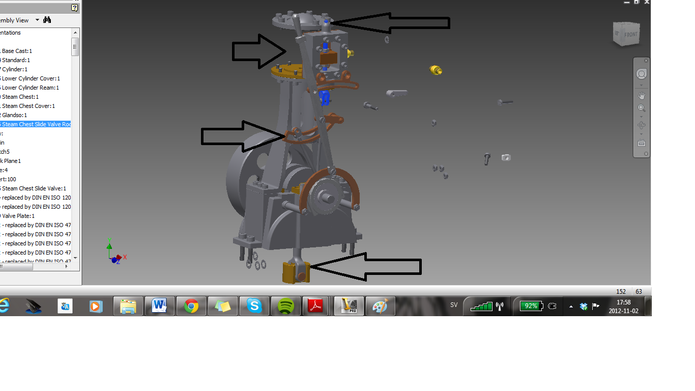
Here i made photo of it, becouse u maby dont need the parts to help me.
you can see where it goes to ****t in the pictures, and i want to limit their motion so they cant "jump" away like that, (when i rotate). "just lock them from going beyond a certain position/angle . The video can be to much help.
Message 10 of 11
11-07-2012
05:45 AM
- Mark as New
- Bookmark
- Subscribe
- Mute
- Subscribe to RSS Feed
- Permalink
- Report
11-07-2012
05:45 AM
BTW: Take a look at "Pack and Go" which is available in Inventor (if you did not use it before). http://wikihelp.autodesk.com/Inventor/enu/2012/Help/0073-Autodesk73/0684-Collabor684/0710-Design_A71...
Message 11 of 11
11-07-2012
06:41 AM
- Mark as New
- Bookmark
- Subscribe
- Mute
- Subscribe to RSS Feed
- Permalink
- Report
11-07-2012
06:41 AM
To preserve the direction of the crankrod (which in some cases moved to opposite direction when rotating the Flyweel:1) can be achieved by adding an angle constraint between the axis of 000.021 Crankrod:1 and axis of 000.005 Lower Cylinder Cover:1 and setting the limits to: maximum = 45 degrees, minimum = -45 degrees. As the reference vector, I used the axis of the 001.002 Crankshaft Center Rod:1.
Reply
Topic Options
- Subscribe to RSS Feed
- Mark Topic as New
- Mark Topic as Read
- Float this Topic for Current User
- Bookmark
- Subscribe
- Printer Friendly Page
Forums Links
Can't find what you're looking for? Ask the community or share your knowledge.
Post to forums
