Community
Inventor Forum
Welcome to Autodesk’s Inventor Forums. Share your knowledge, ask questions, and explore popular Inventor topics.
Turn on suggestions
Auto-suggest helps you quickly narrow down your search results by suggesting possible matches as you type.
Reply
Topic Options
- Subscribe to RSS Feed
- Mark Topic as New
- Mark Topic as Read
- Float this Topic for Current User
- Bookmark
- Subscribe
- Printer Friendly Page
Message 1 of 5
10-15-2012
12:31 AM
- Mark as New
- Bookmark
- Subscribe
- Mute
- Subscribe to RSS Feed
- Permalink
- Report
10-15-2012
12:31 AM
Contacts, Stress analysis
Hello,
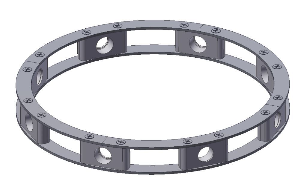
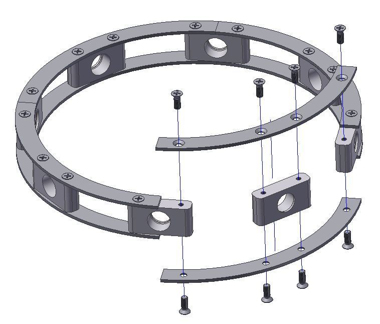
I am trying to calculate flex on a metal ring I have designed and are a bit confused with the contacts that I am getting when using automatic contacts.
Please see the pictures attached for reference.
When I use automatic contacts I get all bonded contacts, but I get the impression that bonded contacts are welded and that is not the case with my design it is bonded using bolts.
Which contacts would you use for this part? Or should I simplify it? Can I run it in the stress simulator?
Cheers!
//Johan
4 REPLIES 4
Message 2 of 5
10-16-2012
01:52 AM
- Mark as New
- Bookmark
- Subscribe
- Mute
- Subscribe to RSS Feed
- Permalink
- Report
Message 3 of 5
10-16-2012
02:55 AM
- Mark as New
- Bookmark
- Subscribe
- Mute
- Subscribe to RSS Feed
- Permalink
- Report
10-16-2012
02:55 AM
I was thinking of this yesterday when I saw the post and am also interested in replies as I've only started dabbling with stress analysis too.
My thoughts (as a discussion point, not a definitive "this is the answer"):
bonded contacts between screw threads (screw OD face and hole ID face)
sliding contacts between the face of each "block" and the mating face of the curved piece
and now, this is where I'm not sure...
sliding contact between CSK screw head and the CSK hole? (so the screws hold the plate to the blocks, as they would in real life).
Is that it, does it need more?
Also interested about the assembly method - without knowing what it's for I admit I'm in the dark, but on the face of it I would have thought you'd offset the top ring 45 degrees to the bottom ring, to prevent having both the top and bottom ring having a joint on the same block - if that makes any sense. Is there a benefit in not offsetting the top to bottom ring?
Sam M.
Inventor and Showcase monkey![]()
Please mark this response as "Accept as Solution" if it answers your question...
If you have found any post to be helpful, even if it's not a direct solution, then please provide that author kudos - spread that love 😄
Message 4 of 5
10-16-2012
07:29 AM
- Mark as New
- Bookmark
- Subscribe
- Mute
- Subscribe to RSS Feed
- Permalink
- Report
10-16-2012
07:29 AM
I would simplify the model by using symmetry - that way you can go to a finer mesh without consuming huge processing times: - split horizontally through the middle - analyze 1/2 of one ring section The model will be 1/16 as complex. - apply a frictionless constraint to each of the faces where a part has been cut in half (but not the free end of the ring section I would try the following contacts - between the rings and the spacer blocks - Separation - between the screw heads and the countersunk surfaces - Separation - between the screw body and the tapped holes - Sliding - No Separation Now model the pre-loading of the threads. If memory serves, the first 3 threads do all the work so: - split the hole at that depth and apply an upward load (assuming upward is toward the ring section) equal to the pre-load of the screw - split the screw body at the point where it enters the threaded hole and again at the depth that you'd split the hole. Apply the pre-load to the screw drawing it downward. Simulate. You might repeat this after changing the contact between the screw head and the countersink to Separation-No Sliding because under load there is friction. I would expect to have to refine the simulation further but this would be a start. Richard
IV 2013 Product Design Suite 64 Bit
Win 7 64 bit
Win 7 64 bit
Message 5 of 5
10-16-2012
11:54 PM
- Mark as New
- Bookmark
- Subscribe
- Mute
- Subscribe to RSS Feed
- Permalink
- Report
10-16-2012
11:54 PM
Hi,
form my experience I would say that chousing how to model constrain in some part schould depand on what results you need. I mean what loads you apply and what areas of construction (model) are most intersting to you.
Sometimes it is not worth an effort to play with rather complicated contact definition because it has rather small influence on are that one is most interested.
If you post files and describe loads you apply and kind of results you are most intersted in it would be helpfull in looking ito case.
Regards,
Cris
Reply
Topic Options
- Subscribe to RSS Feed
- Mark Topic as New
- Mark Topic as Read
- Float this Topic for Current User
- Bookmark
- Subscribe
- Printer Friendly Page
