Community
Inventor Forum
Welcome to Autodesk’s Inventor Forums. Share your knowledge, ask questions, and explore popular Inventor topics.
Turn on suggestions
Auto-suggest helps you quickly narrow down your search results by suggesting possible matches as you type.
Reply
Topic Options
- Subscribe to RSS Feed
- Mark Topic as New
- Mark Topic as Read
- Float this Topic for Current User
- Bookmark
- Subscribe
- Printer Friendly Page
Message 1 of 23
Anonymous
3906 Views, 22 Replies
02-04-2014
06:39 PM
- Mark as New
- Bookmark
- Subscribe
- Mute
- Subscribe to RSS Feed
- Permalink
- Report
02-04-2014
06:39 PM
Common way to dimension depth of a conical surface in drawing is to dimension it over construction ball. I have construction circles in my model sketch. How can I make them available in drawing to dimension to ? Or, is there a better way to accomplish this ? See attachments.
Solved! Go to Solution.
Solved by rdyson. Go to Solution.
22 REPLIES 22
Message 2 of 23
02-04-2014
07:08 PM
- Mark as New
- Bookmark
- Subscribe
- Mute
- Subscribe to RSS Feed
- Permalink
- Report
02-04-2014
07:08 PM
Retrieve model sketch into drawing
or
Sketch in drawing.
Attach your Inventor files here if you can't figure it out.
-----------------------------------------------------------------------------------------
Autodesk Inventor 2019 Certified Professional
Autodesk AutoCAD 2013 Certified Professional
Certified SolidWorks Professional
Message 3 of 23
02-04-2014
11:09 PM
- Mark as New
- Bookmark
- Subscribe
- Mute
- Subscribe to RSS Feed
- Permalink
- Report
02-04-2014
11:09 PM
I have a very similar problem I try to put a dim on a skeched symbol in idw. but I still cant seem to find a way how to do it?
Has anyone had to deal with this? If any solutions are available ?
Message 4 of 23
02-05-2014
04:53 AM
- Mark as New
- Bookmark
- Subscribe
- Mute
- Subscribe to RSS Feed
- Permalink
- Report
02-05-2014
04:53 AM
@Anonymous wrote:
I have a very similar problem I try to put a dim on a skeched symbol in idw. ..
That sounds like a very different problem to me?
Attach your files here.
-----------------------------------------------------------------------------------------
Autodesk Inventor 2019 Certified Professional
Autodesk AutoCAD 2013 Certified Professional
Certified SolidWorks Professional
Message 5 of 23
02-05-2014
09:58 AM
- Mark as New
- Bookmark
- Subscribe
- Mute
- Subscribe to RSS Feed
- Permalink
- Report
02-05-2014
09:58 AM
charles,
Sketched symbols are different. Have you ever dimensioned a dimension? Do you need something welded a certain distance away from the title block?
You might be able to copy your geometry while editing your symbol and paste it in a sketch on a view.
Have you searched the forum? I think this has come up before. You may need to look into "AutoCAD Blocks" instead of Sketched Symbols.
Message 6 of 23
Anonymous
in reply to:
Anonymous
02-06-2014
03:57 PM
- Mark as New
- Bookmark
- Subscribe
- Mute
- Subscribe to RSS Feed
- Permalink
- Report
02-06-2014
03:57 PM
JD,
I figured out how to retrieve model sketch into drawing. But I can't figure out how to display the sketch, or any parts of it. There are a couple of constructin circles in the ID Profile of the model. I'd like to display them in my drawing. I need to dimension depth of the cone in form of dimension from nozzle shoulder to the top of larger circle (gage ball).
Models are attached.
Message 7 of 23
Anonymous
in reply to:
Anonymous
02-06-2014
08:44 PM
- Mark as New
- Bookmark
- Subscribe
- Mute
- Subscribe to RSS Feed
- Permalink
- Report
02-06-2014
08:44 PM

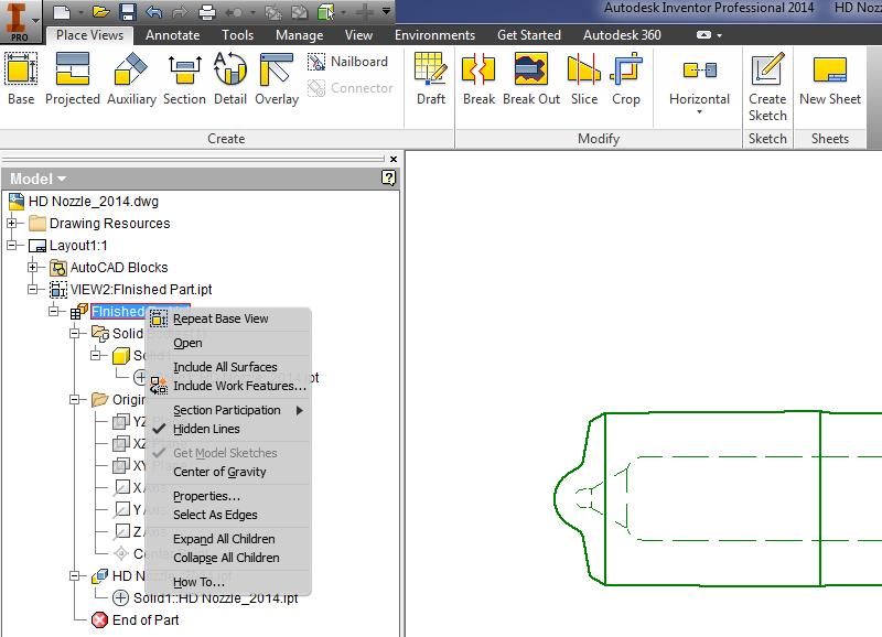
First Step is to "Get Model Sketches" which it sounds like you have done.
Second step is to expand the part-tree, select the sketch you want to show and changes its visibility.
(I think the visibility is linked to the skecth status in the part when you place the view.)
When I made that image the sketch was invisible in the model and I had to set it to visible in the drawing, I just deleted the view, turned on the sketch in the model and re-placed the view, upon getting model sketches this time the circle was immediatlely visible.
Message 8 of 23
Anonymous
in reply to:
Anonymous
02-07-2014
04:52 AM
- Mark as New
- Bookmark
- Subscribe
- Mute
- Subscribe to RSS Feed
- Permalink
- Report
02-07-2014
04:52 AM
I'm still having trouble with this. In the model, I don't see where "make sketch visible in drawing" is. If I right click on the model sketch i can only turn on the "visibility". Is this what you're talking about ? In drawing I see where "get model sketches" is and I did that. But, In the drawing mode I don't see the model sketches in the browser. I can't quite make out your pasted picture (too small) to see what you're trying to show. Please take a look at my attached pictures and figure out what I'm doing wrong. Maybe a more detailed step by step how you do this would also help. I'm new to Inventor so please forgive me if I'm slow at this.
Message 9 of 23
Anonymous
in reply to:
Anonymous
02-07-2014
05:44 AM
- Mark as New
- Bookmark
- Subscribe
- Mute
- Subscribe to RSS Feed
- Permalink
- Report
02-07-2014
05:44 AM
Just a thought ...
In the drawing you can "get model dimensions". This is pretty useless option if you ask me. For example, I can get model sketch dimension that is pointed to a construction circle (my gage ball). However the construction circle does not display in the drawing. So this dimension in a drawing is just hanging out in space pointing to nothing. It would be much better if there was an option not to "get model dimensions" but "get model sketch features" This way one could select any part of the sketch including construction circles, points dimensions, etc. This would be very useful . Seems to me that software people live in their own world without ever consulting customers (users). I'm new to the Inventor and I'm already getting pretty frustrated ...
Message 10 of 23
02-07-2014
07:59 AM
- Mark as New
- Bookmark
- Subscribe
- Mute
- Subscribe to RSS Feed
- Permalink
- Report
02-07-2014
07:59 AM
Seems to work for me. Note that the sketch has to be normal to the view you want to show it in.
PDSU 2016
Message 11 of 23
Anonymous
in reply to:
Anonymous
02-07-2014
03:43 PM
- Mark as New
- Bookmark
- Subscribe
- Mute
- Subscribe to RSS Feed
- Permalink
- Report
02-07-2014
03:43 PM
Thanks guys for trying to help out.
Yes importing model sketch into the drawing works. However, this is not what I'm trying to do. I'm trying to come up with a system where my model is fully parametric (variable). This is why I'm employing excel to drive my manufacturing stages of a part. That appears to work. Drawings of the different manufacturing stages of the model are very important. This is what I send to my blank suppliers and post on a shop floor at the various manufacturing stations. It is our basic and required process control documentation.
It's just like I thought, when you import the model sketch into the drawing, it shows the whole sketch and all it's features. Where I only wanted to display a part of it, like a construction circle. In diesel fuel systems industry, we make meny components that require conical surfaces. Most common (and best) way to dimension location of a cone is to use a gage ball. This is also how the parts are getting measured (over a physical gage ball).
JD suggested I could also do some sketching in drawings. This is not an answer either. With and average model, there are meny drawings associated and each one representing a differnt stage of manufacturing step. Quite often models need revisions and changes. I don't want to be making sketches on all of the resulting drawings. Plus I don't even see a way to attach my sketches to the part in the drawing. So when models gets revised, the drawing sketches need to automatically change as well. When you sketch something in a drawing, it is just an independent sketch and does not belong to a variable model.
Ability to retrieve a part of a model sketch would be a good solution. This is already available for dimensions and model work features. Why not for model sketch features ???.
At this point I'm not sure what to do. Since the demise of Mechanical Desktop I'm beeing pushed to come up with alternatives, but I'm starting to have doubts in Inventor ...
For everyones info. In Mechanical Desktop, I could easily add a ball as a separate part and include it in my drawings. The process takes a few seconds. In the individual drawing views I can turn the visibility on and off as I need it. Process was painless and quick. Seems like the Inventor is a step back in meny aspects.
I'm wondering if anyone from Autodesk development team is reading any of these posts. They can sure use some improvemnts ...
Message 12 of 23
02-07-2014
04:00 PM
- Mark as New
- Bookmark
- Subscribe
- Mute
- Subscribe to RSS Feed
- Permalink
- Report
02-07-2014
04:00 PM
In the drawing, if you select a view before starting the sketch it will be attached to the view and you can project lines, etc. from the part.
Or
Make another sketch in the part - project your circle from the sketch you constructed everything in, now you have a sketch with only the "ball" that you can import.
And the best solution
Do it the way you used to do it - the way it actually gets made: Make a ball and put your part into an Assembly with that ball and make the drawing of the assembly.
Getting the right answers is about asking the right questions - this has been going along trying to help get your sketch into your drawing, if you had said "I want to add a gauge ball in my drawing" from the start you would realize that this isn't an aspect where Inventor is a step back.
Message 14 of 23
02-08-2014
06:53 AM
- Mark as New
- Bookmark
- Subscribe
- Mute
- Subscribe to RSS Feed
- Permalink
- Report
02-08-2014
06:53 AM
@Anonymous wrote:
.... Plus I don't even see a way to attach my sketches to the part in the drawing. So when models gets revised, the drawing sketches need to automatically change as well. When you sketch something in a drawing, it is just an independent sketch and does not belong to a variable model.
..but I'm starting to have doubts in Inventor ...
You have a longgggg way to go to learn Inventor techniques. How long did you use MDT. Do you have any idea how long it took you to master MDT? Because I take students through 4 yrs of study (at one time with MDT) I end up with seniors in the spring who almost seem to read my mind as I start making suggestions to freshman in the following fall where I forget they aren't my pro seniors. I am immediately transported back to my first stumbling steps going from MDT to Inventor. We tend to forget what it took to master a tool. (the first semester we started with Inventor I told my students, "We will look at this Inventor program, but MDT is my favored program. By the middle of the semester we no longer even bothered to open MDT - it was obvious an antiquated beast.
A year from now you will come back and revisit this thread and chuckle with the same realization.
Push forward knowing that there is an easy and logical way in Inventor - a logical way that makes MDT an antiquated beast. A beast that should have been put to rest 12 years ago.
-----------------------------------------------------------------------------------------
Autodesk Inventor 2019 Certified Professional
Autodesk AutoCAD 2013 Certified Professional
Certified SolidWorks Professional
Message 15 of 23
Anonymous
in reply to:
Anonymous
02-09-2014
04:54 PM
- Mark as New
- Bookmark
- Subscribe
- Mute
- Subscribe to RSS Feed
- Permalink
- Report
02-09-2014
04:54 PM
Guys,
Your help is greatly appreciated.
I suppose it took me a while to learn Mechanical Desktop. Learning goes on for ever and pretty much unnoticed, untill you look back and really think about it. Thank you all for your patience with me.
Message 16 of 23
02-09-2014
05:11 PM
- Mark as New
- Bookmark
- Subscribe
- Mute
- Subscribe to RSS Feed
- Permalink
- Report
02-09-2014
05:11 PM
It's taking me a while to get the hang of this. I'm still having trouble with just being able to display model sketches in my drawings. They don't even show up in my drawing browser. Not sure what I'm doing wrong.
The attached drawing looks pretty good. This is exactly what I was after. In the drawing there is a detail "B" and it shows the 1.5mm ball. How would I also display the larger 2.5mm ball in that view ??? Can you step by step let me know how to do this ?
Message 17 of 23
Anonymous
in reply to:
Anonymous
02-09-2014
09:01 PM
- Mark as New
- Bookmark
- Subscribe
- Mute
- Subscribe to RSS Feed
- Permalink
- Report
02-09-2014
09:01 PM
It appears that due to your part being an iPart there is no 'sketches' in the model files for the drawing to retrieve.
I'm not sure how best to handle that (there may be a quick fix)
Otherwise my only suggestion is to follow reality... this drawing needs to be based off an assembly file as you want multiple parts to be on the sheet. (and on the factory floor the guys will be making an 'assembly' to perform any measures with the gage balls)


Message 19 of 23
02-10-2014
06:12 PM
- Mark as New
- Bookmark
- Subscribe
- Mute
- Subscribe to RSS Feed
- Permalink
- Report
02-10-2014
06:12 PM
Thanks. This is helpful. For some reason, I can only show the small or the large but not both balls at the same tine ???
Reply
Topic Options
- Subscribe to RSS Feed
- Mark Topic as New
- Mark Topic as Read
- Float this Topic for Current User
- Bookmark
- Subscribe
- Printer Friendly Page
Forums Links
Can't find what you're looking for? Ask the community or share your knowledge.
Post to forums
