Community
- Forums Home
- >
- Inventor Community
- >
- Inventor Forum
- >
- Re: Bring subassembly into assembly at precise location
Inventor Forum
Welcome to Autodesk’s Inventor Forums. Share your knowledge, ask questions, and explore popular Inventor topics.
Turn on suggestions
Auto-suggest helps you quickly narrow down your search results by suggesting possible matches as you type.
Reply
Topic Options
- Subscribe to RSS Feed
- Mark Topic as New
- Mark Topic as Read
- Float this Topic for Current User
- Bookmark
- Subscribe
- Printer Friendly Page
Message 1 of 6
01-29-2013
02:27 PM
- Mark as New
- Bookmark
- Subscribe
- Mute
- Subscribe to RSS Feed
- Permalink
- Report
01-29-2013
02:27 PM
Bring subassembly into assembly at precise location
Can anyone think of the best way to do this? To simplify lets say I have a square plate, vertically positioned. I have a square tube that I wish to cantilever off the plate and weld into place horizontally. EVERY time I bring that square tube in (lets say its a subassembly of its own rather than a part), it is precisely 1 inch below the top of the plate and 1 in in from the left edge.
Can anyone think of a way to make that happen where maybe I bring the part in and click on the two faces, it knows the other two contraints? Thanks...
5 REPLIES 5
Message 2 of 6
01-29-2013
05:23 PM
- Mark as New
- Bookmark
- Subscribe
- Mute
- Subscribe to RSS Feed
- Permalink
- Report
01-29-2013
05:23 PM
Sounds like a job for iLogic to me. Or, if you're more comfortable in VBA, that should work, too. You might try posting in the Inventor Customization group, too.
Sam B
Inventor 2012 Certified Professional
Please click "Accept as Solution" if this response answers your question.
-------------------------------------------------------------------------------------
Inventor Professional 2013 SP1.1 Update 1
Windows XP Pro 32-bit, SP3
HP EliteBook 8730w; 4 GB RAM; Core™ 2 Duo T9400 2.53 GHz; Quadro FX2700M
SpaceExplorer/SpaceNavigator NB, driver 3.7.18
still waiting for a foreshortened radius dimensioning tool in Drawing Manager
Message 3 of 6
01-29-2013
09:33 PM
- Mark as New
- Bookmark
- Subscribe
- Mute
- Subscribe to RSS Feed
- Permalink
- Report
01-29-2013
09:33 PM
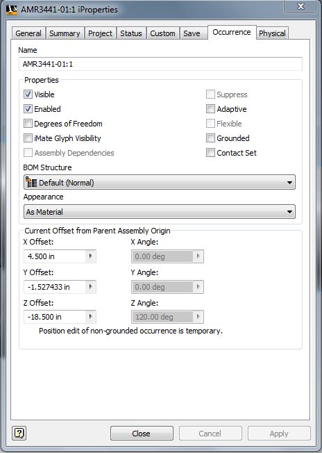
I watch Kevin Schneider work with a plastic assembly a couple few AU's ago and he was located the assemblies using the XZY data in the occurance tab of a part within an assembly.
I wish I had kept notes of the class, but this data is only generated once the part is placed in a IAM and not in the IPT file.
Inventor 2020, In-Cad, Simulation Mechanical
Just insert the picture rather than attaching it as a file
Did you find this reply helpful ? If so please use the Accept as Solution or Kudos button below.
Delta Tau Chi ΔΤΧ
Message 4 of 6
01-30-2013
04:56 AM
- Mark as New
- Bookmark
- Subscribe
- Mute
- Subscribe to RSS Feed
- Permalink
- Report
01-30-2013
04:56 AM
This is exactly what iMates are for. I'm sure there's a tutorial on AutoDesk somewhere for them.
Mike (not Matt) Rattray

Message 5 of 6
01-31-2013
09:46 AM
- Mark as New
- Bookmark
- Subscribe
- Mute
- Subscribe to RSS Feed
- Permalink
- Report
01-31-2013
09:46 AM
Thanks yall. I was able to add some iMates to the parts to get them to work. Can anyone explain to me real fast what the "matching" means when defining an iMate and giving it a name? I have an idea but I'm not positive I'm right. Thanks.
Message 6 of 6
01-31-2013
10:49 PM
- Mark as New
- Bookmark
- Subscribe
- Mute
- Subscribe to RSS Feed
- Permalink
- Report
01-31-2013
10:49 PM
This should help: http://wikihelp.autodesk.com/Inventor/enu/2013/Help/1310-Autodesk1310/1655-Assembli1655/1656-Build_a...
Inventor 2020, In-Cad, Simulation Mechanical
Just insert the picture rather than attaching it as a file
Did you find this reply helpful ? If so please use the Accept as Solution or Kudos button below.
Delta Tau Chi ΔΤΧ
Reply
Topic Options
- Subscribe to RSS Feed
- Mark Topic as New
- Mark Topic as Read
- Float this Topic for Current User
- Bookmark
- Subscribe
- Printer Friendly Page
