Community
- Forums Home
- >
- Fabrication Products Community
- >
- Fabrication CADmep Forum
- >
- Re: Step Down Connector not drawing accurately
Fabrication CADmep Forum
Welcome to Autodesk’s Fabrication CADmep Forums. Share your knowledge, ask questions, and explore popular Fabrication CADmep topics.
Turn on suggestions
Auto-suggest helps you quickly narrow down your search results by suggesting possible matches as you type.
Reply
Topic Options
- Subscribe to RSS Feed
- Mark Topic as New
- Mark Topic as Read
- Float this Topic for Current User
- Bookmark
- Subscribe
- Printer Friendly Page
Message 1 of 8
Anonymous
1321 Views, 7 Replies
09-03-2013
09:45 PM
- Mark as New
- Bookmark
- Subscribe
- Mute
- Subscribe to RSS Feed
- Permalink
- Report
09-03-2013
09:45 PM
Step Down Connector not drawing accurately
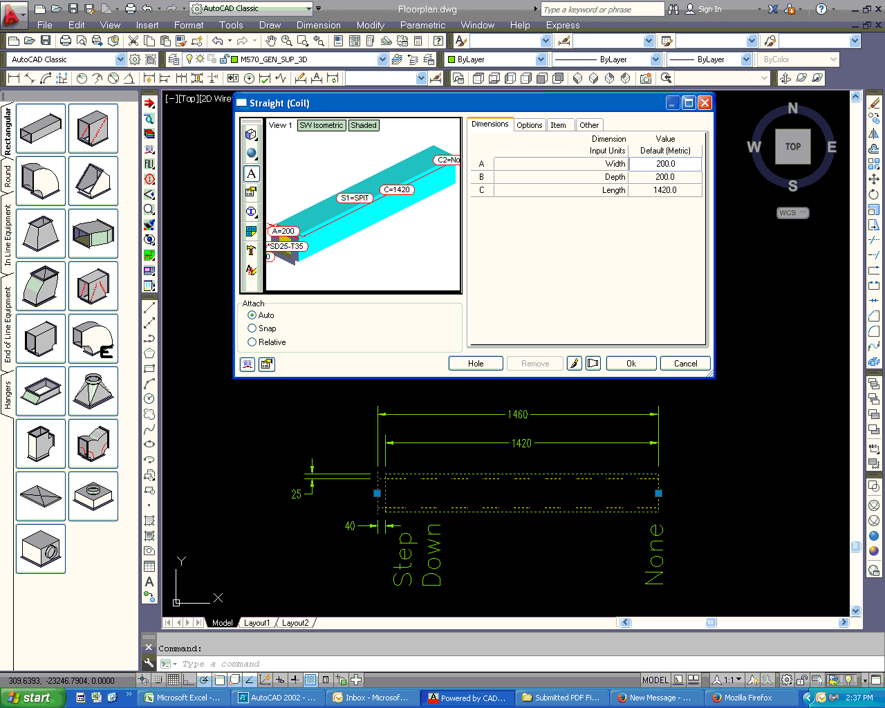
We are using CADMep on AutoCAD 2013. We are having a problem drawing the Step Down Connectors for ductwork properly. We encountered this problem in CADDuct Solids as well, the 2002 version of CADDuct drew it correctly.
-We have our material for ductwork come in at 1500 wide rolls.
-When we add flanges to our ductwork we take off the amount required to form the flange
-When we use step down connectors it does not take off the required amount, creating length discrepencies.
For our Step Down 25 TDF35 Connection we need to take of 80mm from the sheet, 25 for the step down and 55 for the flange, This should leave a piece of duct 1420 Long, with no connection on other end. When we draw it in CADMep, it draws the length from the case, not the step down. Is there a way around this? We enter the length at 1420, but draws it at 1460.
We have encountered this problem before, with CADDuct Solids and were wondering if it has been addressed?
7 REPLIES 7
Message 2 of 8
09-09-2013
03:19 AM
- Mark as New
- Bookmark
- Subscribe
- Mute
- Subscribe to RSS Feed
- Permalink
- Report
09-09-2013
03:19 AM
Could you post that DWG file so we can see how your connector is defined.
Thanks
Andy Robins
Engineering Manager
Message 3 of 8
09-10-2013
01:26 PM
- Mark as New
- Bookmark
- Subscribe
- Mute
- Subscribe to RSS Feed
- Permalink
- Report
09-10-2013
01:26 PM
You cannot add the extension to the connector as this gets added to the length.Take that off and it will be good other than the graphics.This has been this way for the 12yrs I've been using the program
Message 4 of 8
Anonymous
in reply to:
Anonymous
09-11-2013
11:02 PM
- Mark as New
- Bookmark
- Subscribe
- Mute
- Subscribe to RSS Feed
- Permalink
- Report
09-11-2013
11:02 PM
Just to show I'm not an expert (I know very little about everything), to understand this post correctly, would a stepdown connector be like a flush bushing in plumbing? Hi Bob, happy retirement.
Message 5 of 8
Anonymous
in reply to:
Anonymous
09-11-2013
11:05 PM
- Mark as New
- Bookmark
- Subscribe
- Mute
- Subscribe to RSS Feed
- Permalink
- Report
09-11-2013
11:05 PM
ok I just noticed the pix and see its for transitioning from lined duct to unlined. You learn something new every day. I have always used a taper/transition in my former life. Ah metric, those were the days.....but then I was hand drafting and graphics were no problemo
Message 6 of 8
Anonymous
in reply to:
Anonymous
09-12-2013
05:52 PM
- Mark as New
- Bookmark
- Subscribe
- Mute
- Subscribe to RSS Feed
- Permalink
- Report
09-12-2013
05:52 PM
Alright, we will take the extension off, and just change the way we show our step down connectors. If this is the way its been done for 12 years, should work for us.
Message 7 of 8
Anonymous
in reply to:
Anonymous
09-13-2013
07:29 PM
- Mark as New
- Bookmark
- Subscribe
- Mute
- Subscribe to RSS Feed
- Permalink
- Report
09-13-2013
07:29 PM
Have not retired yet,just took some months off((deserving I believe after 30 years)I have some unfinished business before I think about retirement.Back to the original post,If you delete the ext and look at the developments and the x or y you will see that it is correct.
Just have to deal with the graphics.
Message 8 of 8
Anonymous
in reply to:
Anonymous
09-16-2013
06:44 AM
- Mark as New
- Bookmark
- Subscribe
- Mute
- Subscribe to RSS Feed
- Permalink
- Report
09-16-2013
06:44 AM
Good to hear there's life in the old dog yet!
Ray Couzens
President and CEO
CC2BL INC | Virtual Design and Lean Construction Services
We imagine a construction world where all project aspects have value to the
Owner and nothing is wasted!
Cell: (303) 514-1862
Direct/fax: (856) 269-2922
Email:
support@couzenscad2bimleeds.com
On the web:
http://www.couzenscad2bimleeds.com
Follow me on
www.twitter.com/@fishandchips47
Minimize Risk - Maximize profits
This message and any attachments from the firm of CC2BL INC
May contain proprietary, confidential, trade secret or privileged
information and is solely
For the use of the intended recipient(s). If you are not the intended
recipient
or a person responsible for delivering this message to the intended
recipient
be aware that any unauthorized review disclosure, copying, distribution
or use of the contents of this message is strictly prohibited.
If you have received this message in error, please destroy all copies of the
original message
Immediately, and notify us at 856-269-2922
or via electronic mail at support@couzenscad2bimleeds.com
Reply
Topic Options
- Subscribe to RSS Feed
- Mark Topic as New
- Mark Topic as Read
- Float this Topic for Current User
- Bookmark
- Subscribe
- Printer Friendly Page
Forums Links
Can't find what you're looking for? Ask the community or share your knowledge.
Post to forums
