Community
- Forums Home
- >
- AutoCAD Plant 3D Community
- >
- AutoCAD Plant 3D Forum
- >
- Re: Small bore pipe support (dummy leg/stanchion)
AutoCAD Plant 3D Forum
Welcome to Autodesk’s AutoCAD Plant 3D Forums. Share your knowledge, ask questions, and explore popular AutoCAD Plant 3D topics.
Turn on suggestions
Auto-suggest helps you quickly narrow down your search results by suggesting possible matches as you type.
Reply
Topic Options
- Subscribe to RSS Feed
- Mark Topic as New
- Mark Topic as Read
- Float this Topic for Current User
- Bookmark
- Subscribe
- Printer Friendly Page
Message 1 of 7
01-21-2013
01:17 PM
- Mark as New
- Bookmark
- Subscribe
- Mute
- Subscribe to RSS Feed
- Permalink
- Report
01-21-2013
01:17 PM
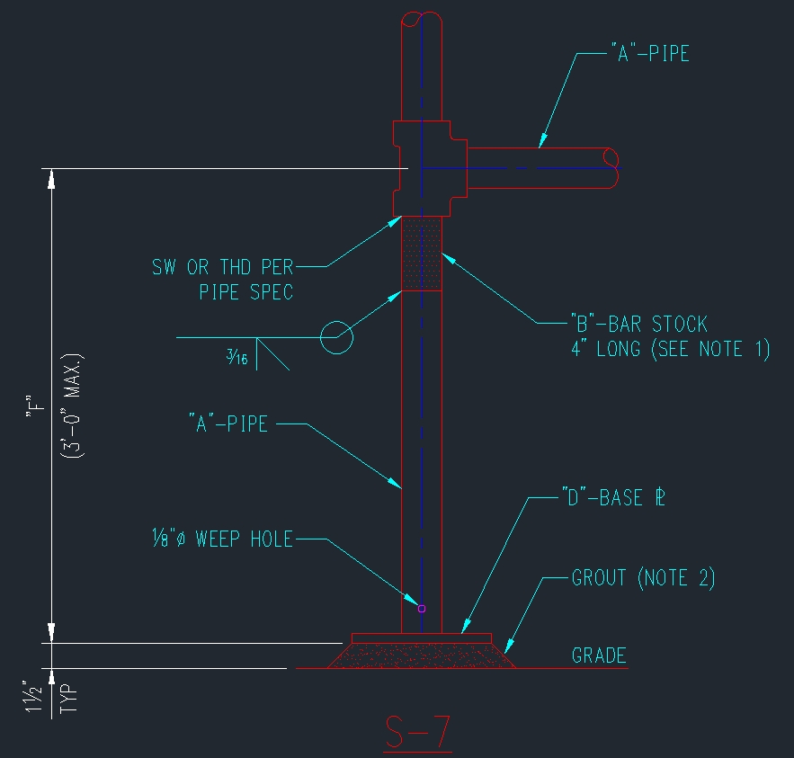
I'm a Plant 3D newbie. We use the attached support quite a bit. I'm not sure how to build this within P3D. One thing I have tried is to create an AutoCAD entity and convert it to a pipe support. This will attach it to the SW tee, but I'll still have the "drip" symbol.
Any suggestions would be appreciated.
Solved! Go to Solution.
Solved by quentin.contreras. Go to Solution.
6 REPLIES 6
Message 2 of 7
01-24-2013
02:32 PM
- Mark as New
- Bookmark
- Subscribe
- Mute
- Subscribe to RSS Feed
- Permalink
- Report
01-24-2013
02:32 PM
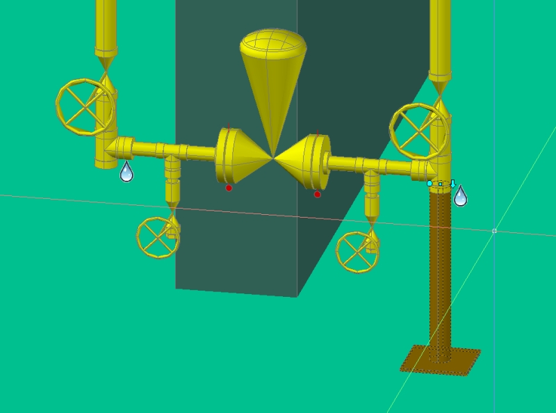
Can you provide a screen shot of what you have converted to pipe support? I would like to see where the "drip", disconnect marker, is being placed.
If my post answers your question, please mark it as an Accepted Solution, so that others can find answers quickly!
![]()
Quentin Contreras
Technical Support Specialist
Message 3 of 7
01-25-2013
08:48 AM
- Mark as New
- Bookmark
- Subscribe
- Mute
- Subscribe to RSS Feed
- Permalink
- Report
01-25-2013
08:48 AM
Attached is a JPG.
My process for creating the support was to make an AutoCAD object, move it to the location, then use the PLANTPIPESUPPORTCONVERT command and chose the socket of the tee as the insertion point.
Thank you.
Message 4 of 7
02-06-2013
05:46 PM
- Mark as New
- Bookmark
- Subscribe
- Mute
- Subscribe to RSS Feed
- Permalink
- Report
02-06-2013
05:46 PM
Quentin,
I didn't realize that you were the same person I had talked with on the phone, the other day, about my other issue with my line numbers not working. ![]()
You haven't happened to make any progress on this issue have you?
Eric
Message 5 of 7
02-07-2013
04:54 PM
- Mark as New
- Bookmark
- Subscribe
- Mute
- Subscribe to RSS Feed
- Permalink
- Report
02-07-2013
04:54 PM
I am sorry I did not get back to you before now. The easiest thing to do would be, for the threaded 3 way tee is just to place a plug. Then you could model your our support and convert support. This would also apply if you are using a SW tee.

However, then you would have a plug that would show up in you BOM. The other option would be is the generate a custom tee with one end plugged.

You can refer to this web link on creating Custom Companents.
http://www.pdoteam.com/2011/10/custom-components-in-autocad-plant-3d/
Let me know if this helps.
If my post answers your question, please mark it as an Accepted Solution, so that others can find answers quickly!
![]()
Quentin Contreras
Technical Support Specialist
Message 6 of 7
02-11-2013
05:07 PM
- Mark as New
- Bookmark
- Subscribe
- Mute
- Subscribe to RSS Feed
- Permalink
- Report
02-11-2013
05:07 PM
Just checking to see if this helped or were you able to find another solution.
If my post answers your question, please mark it as an Accepted Solution, so that others can find answers quickly!
![]()
Quentin Contreras
Technical Support Specialist
Message 7 of 7
02-13-2013
08:29 PM
- Mark as New
- Bookmark
- Subscribe
- Mute
- Subscribe to RSS Feed
- Permalink
- Report
02-13-2013
08:29 PM
Hello Quentin. I finally got around to trying one of your suggestions. I took a round plug and changed it's size to mimic a 4" long piece of round bar. This seems to fix the "drip" connection. As soon as I attach my pipe support to the plug, the "drip" reappears, but is only visable if you select the support.
For the iso's, I can probably just create a new iso symbol for the round bar so that it includes the "duck" and then just fake the duck in the model. If that makes sense.
Reply
Topic Options
- Subscribe to RSS Feed
- Mark Topic as New
- Mark Topic as Read
- Float this Topic for Current User
- Bookmark
- Subscribe
- Printer Friendly Page

