Community
- Forums Home
- >
- AutoCAD Plant 3D Community
- >
- AutoCAD Plant 3D Forum
- >
- Re: Problems with ISO - Lined Flange don't show!
AutoCAD Plant 3D Forum
Welcome to Autodesk’s AutoCAD Plant 3D Forums. Share your knowledge, ask questions, and explore popular AutoCAD Plant 3D topics.
Turn on suggestions
Auto-suggest helps you quickly narrow down your search results by suggesting possible matches as you type.
Reply
Topic Options
- Subscribe to RSS Feed
- Mark Topic as New
- Mark Topic as Read
- Float this Topic for Current User
- Bookmark
- Subscribe
- Printer Friendly Page
Message 1 of 4
01-05-2012
10:38 AM
- Mark as New
- Bookmark
- Subscribe
- Mute
- Subscribe to RSS Feed
- Permalink
- Report
01-05-2012
10:38 AM
Problems with ISO - Lined Flange don't show!
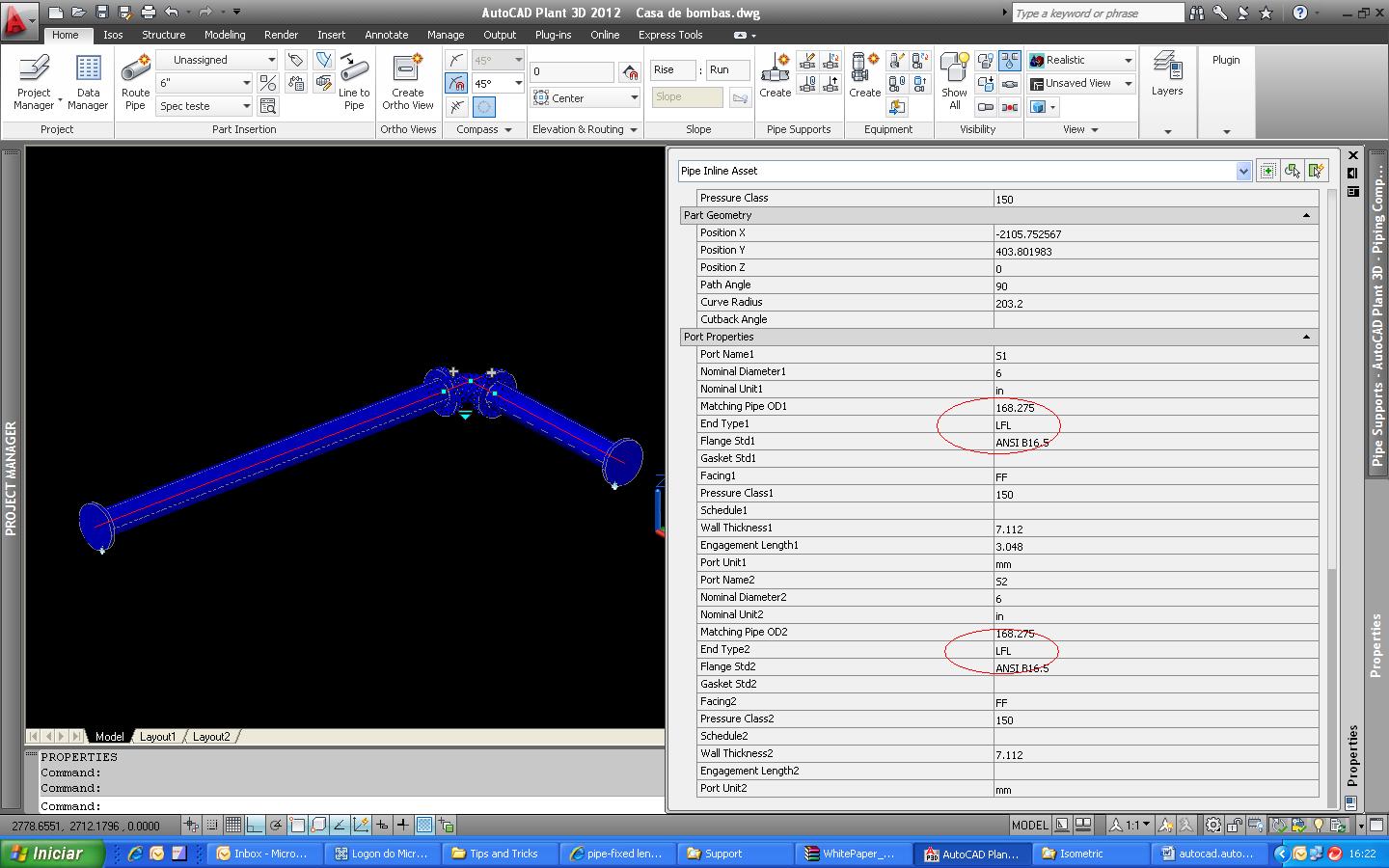
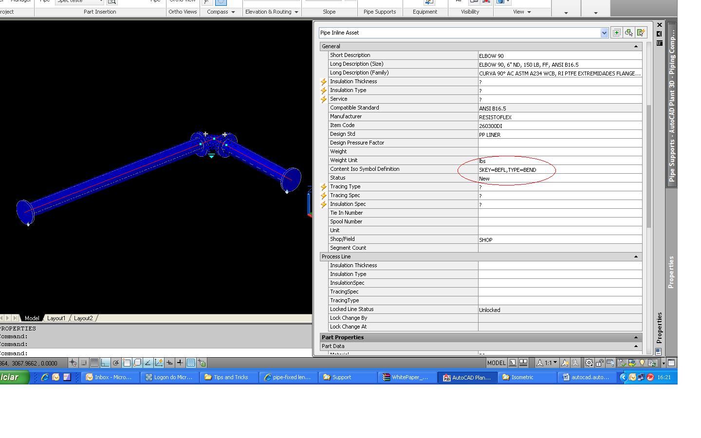
Hello at all, I downloaded the catalog Resistoflex PP lined Pipes and Fittings and i've got a problem with flange (EndType LFL) representation in isometric. Lined flanges don't be showed, see attached files. I know that in Autocad plant 3d 2012, the symbol for fixed-pipe length is not a default symbol, but i know how to solve it. My main problem is how to make the isometric show the flanged fittings correctly. Someone have any idea? Thanks!
3 REPLIES 3
Message 2 of 4
01-05-2012
05:55 PM
- Mark as New
- Bookmark
- Subscribe
- Mute
- Subscribe to RSS Feed
- Permalink
- Report
01-05-2012
05:55 PM
If you look at IsoSkeyAcadBlockMap.xml in the /Isometrics/ folder of your project, that has the mapping for the SKEY's to the ACAD block it will draw in Isometric.
The default shows this: <SkeyMap SKEY = "BE??" AcadBlock ="Elbow"/>
It means that anything with an SKEY starting with BE and ending in a wildcard will draw the Elbow symbol. To change this, you will need to add your own symbol in the Isometrics settings, and change the AcadBlock entry above to point to the name of your new block.
So lets say you draw an elbow with flanges on it, and called it "ElbowFlange", so the above line would need to change to look this this:
<SkeyMap SKEY = "BE??" AcadBlock ="ElbowFlange"/>
To add the new symbol, go into the project properties, and open up the Isometrics options, and in the last dialog for Isometrics (where you setup the Title Block" there is a button for Isometric Symbols. This is where you add the new Iso block symbology. Draw it as a plan flat 2D item, just look at one of the other Elbow blocks, and give it a new name with the symbology you want.
If you want screenshots, let me know.
Tomislav Golubovic
Technical Specialist - Plant and Infrastructure
Autodesk Australia / New Zealand
Autodesk, Inc.
Autodesk ANZ YouTube Channel
Message 3 of 4
01-06-2012
09:48 AM
- Mark as New
- Bookmark
- Subscribe
- Mute
- Subscribe to RSS Feed
- Permalink
- Report
01-06-2012
09:48 AM
Firstly, thanks for your reply.
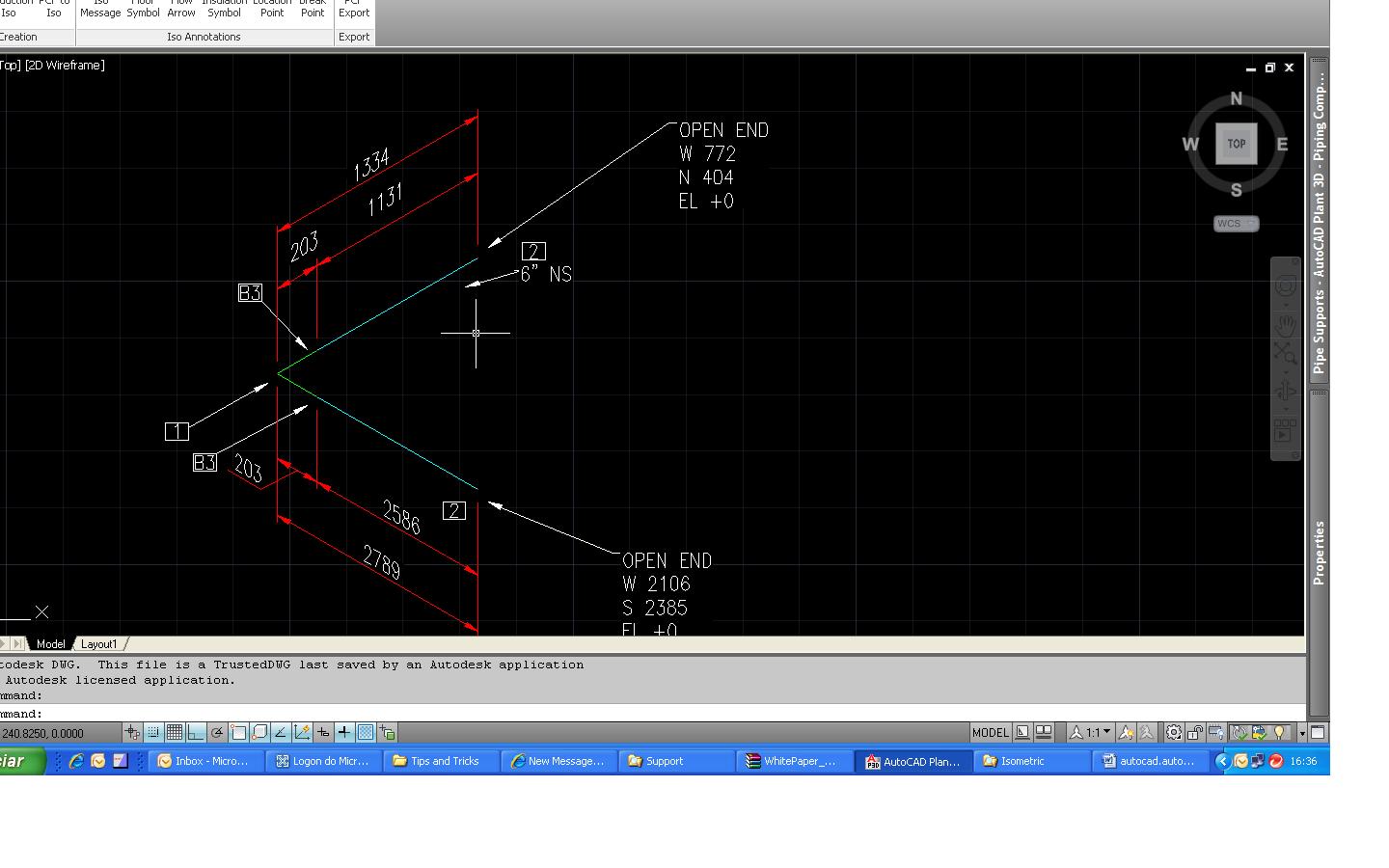
I did what you said and it worked. But I still have a little problem, the connection between the flanges (flanged elbow and pipe fixed length) displayed in the isometric is being shown in different planes, see attached file.
How can I fix it?
Thanks,
Message 4 of 4
08-21-2012
01:24 PM
- Mark as New
- Bookmark
- Subscribe
- Mute
- Subscribe to RSS Feed
- Permalink
- Report
Reply
Topic Options
- Subscribe to RSS Feed
- Mark Topic as New
- Mark Topic as Read
- Float this Topic for Current User
- Bookmark
- Subscribe
- Printer Friendly Page
