Community
- Forums Home
- >
- AutoCAD Plant 3D Community
- >
- AutoCAD Plant 3D Forum
- >
- Re: Isometrich problems with endcodes "FFBNG"
AutoCAD Plant 3D Forum
Welcome to Autodesk’s AutoCAD Plant 3D Forums. Share your knowledge, ask questions, and explore popular AutoCAD Plant 3D topics.
Turn on suggestions
Auto-suggest helps you quickly narrow down your search results by suggesting possible matches as you type.
Reply
Topic Options
- Subscribe to RSS Feed
- Mark Topic as New
- Mark Topic as Read
- Float this Topic for Current User
- Bookmark
- Subscribe
- Printer Friendly Page
Message 1 of 2
10-02-2012
05:57 AM
- Mark as New
- Bookmark
- Subscribe
- Mute
- Subscribe to RSS Feed
- Permalink
- Report
10-02-2012
05:57 AM
Isometrich problems with endcodes "FFBNG"
Hello ,
so now the question from the experts:
Where is the dimension in controlled Isometric module and how it is configured?
I suspect that this is taking place in the "IsoConfig.xml". I've created a end connection with the designation "FFBNG" for flange bolt kit and valve. My fear is that in the "IsoConfig.xml" the points for the dimension are only to the end connections "FL" set and therefore there is no dimension on my isometric. Furthermore, a flange of the end "FFBNG" is inserted upside in isometric.
In the attached picture you can see in 1. the correct representation with flange and valve in "FL" and in 2nd the not quite correct view and with orphaned dimension. This was already discussed in the forum but not released. I'm mint Plant 2013 and all Hotfixes and Service Packs. Request for confirmation or configuration change best regards Hartmut
-
If my reply was helpful, please give a "Kudo" or click the "Accept as Solution" button below (or both).
If my reply was helpful, please give a "Kudo" or click the "Accept as Solution" button below (or both).
Hartmut Eger
Senior Engineer
Anlagenplanung + Elektotechnik
XING | LinkedIn
1 REPLY 1
Message 2 of 2
10-02-2012
11:40 AM
- Mark as New
- Bookmark
- Subscribe
- Mute
- Subscribe to RSS Feed
- Permalink
- Report
10-02-2012
11:40 AM
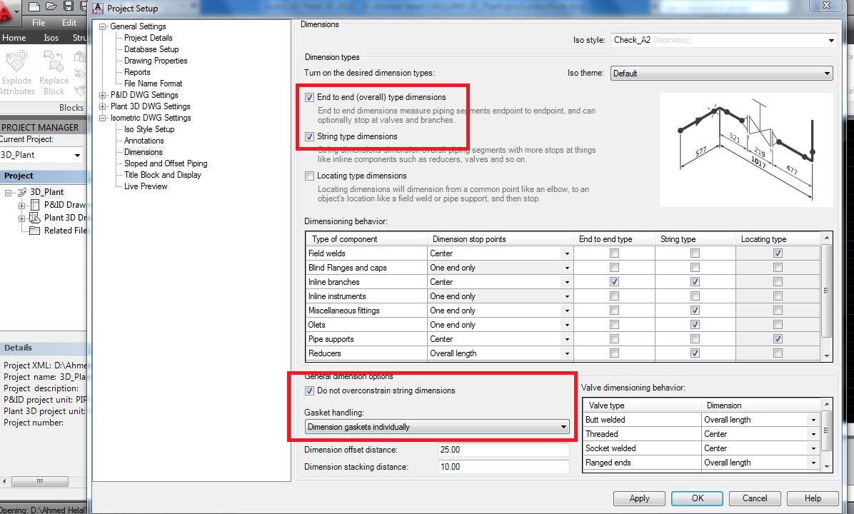
Regarding The Dimension issue i saw in your generated isometric the dimension for gasket not shown in the Drawing the Solution for that in the attached file and for the another issue direction for flange in wrong it mean something wrong in your Model better to delete and draw again
Regards
Ahmed Helal
Reply
Topic Options
- Subscribe to RSS Feed
- Mark Topic as New
- Mark Topic as Read
- Float this Topic for Current User
- Bookmark
- Subscribe
- Printer Friendly Page

