Community
- Forums Home
- >
- AutoCAD Plant 3D Community
- >
- AutoCAD Plant 3D Forum
- >
- As a symbol placed in componetes Tie-In Olets type within piping isometrics
AutoCAD Plant 3D Forum
Welcome to Autodesk’s AutoCAD Plant 3D Forums. Share your knowledge, ask questions, and explore popular AutoCAD Plant 3D topics.
Turn on suggestions
Auto-suggest helps you quickly narrow down your search results by suggesting possible matches as you type.
As a symbol placed in componetes Tie-In Olets type within piping isometrics
3 REPLIES 3
SOLVED
Reply
Topic Options
- Subscribe to RSS Feed
- Mark Topic as New
- Mark Topic as Read
- Float this Topic for Current User
- Bookmark
- Subscribe
- Printer Friendly Page
Message 1 of 4
10-14-2013
12:39 PM
- Mark as New
- Bookmark
- Subscribe
- Mute
- Subscribe to RSS Feed
- Permalink
- Report
10-14-2013
12:39 PM
Good afternoon fellow
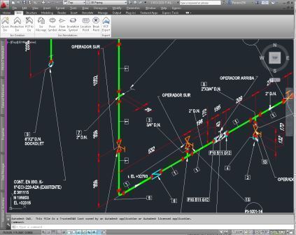
I am designing pipes with pipe interconnection points existing within the properties of the component ( Tee, Elbow, Sockolets , WELDOLETS , etc. . ) Filled the " Tie In Number" and put the number that corresponds to that interconexón as did the in Tie symbol in the file " IsoSymbolStyle.dwg " because isoconfig.xml modify the file by adding a " ComponentScheme " within the " Themes" and " AnnotationSchemes " and also add a ' Filter " with the following legend :
< Filter Name = " TieIn " Value = "Type LIKE ' T * ' OR Type LIKE ' CROSS * ' OR Type LIKE ' Reducer * ' OR Type LIKE ' * FLANGE ' OR Type LIKE ' Elbow * ' OR Type LIKE ' Olet * ' " / >
My problem is that when I generate the isometric of pipe not recognize anything but the " Olets " and does not generate the symbol , but the other components if generated . What you should not recognize me Components " Olets2 " or perhaps will be my syntax wrong ? .
Solved! Go to Solution.
Solved by Matellezm. Go to Solution.
3 REPLIES 3
Message 2 of 4
10-15-2013
02:17 PM
- Mark as New
- Bookmark
- Subscribe
- Mute
- Subscribe to RSS Feed
- Permalink
- Report
10-15-2013
02:17 PM
I don’t know if I’m completely following your workflow description here. Basically your isometric configuration and customization isn’t working properly yet it appears. It may be a need to get the proper SKEYs associated with each component. Please review this helpful whitepaper on Isometrics:
http://docs.autodesk.com/PLNT3D/2014/ENU/De-mystifying%20AutoCAD%20Plant%203D%20Isometrics.pdf
Also, this section on Isometric Configuration (Advanced) in the online Help documentation has a lot of info.
http://docs.autodesk.com/PLNT3D/2014/ENU/filesPLNT3D/GUID-4923622A-F06C-4EA9-AE21-F3E4CAC841A4.htm
The images you posted here are hard to see clearly. FYI.
Martin Stewart
AEC Support Specialist
Message 3 of 4
10-16-2013
09:47 AM
- Mark as New
- Bookmark
- Subscribe
- Mute
- Subscribe to RSS Feed
- Permalink
- Report
10-16-2013
09:47 AM
Thanks for taking my question but I solved my problem and their answers were not my solution.
Message 4 of 4
07-25-2018
07:44 AM
- Mark as New
- Bookmark
- Subscribe
- Mute
- Subscribe to RSS Feed
- Permalink
- Report
07-25-2018
07:44 AM
Miguel,
I am interested in doing this in my project as well. Please tell me, how did you resolve the issue?
Would you have the component scheme text line from your xml file?
To confirm, you added a symbol in the isosymbolstyle.dwg for your custom Tie-Point (with Tie In Number attribute). Then you added a component scheme filter in the xml file to read the Tie In Number attribute and add a iso symbol when that attribute has a value filled out? Am I on the right track?
Thanks!!
Erin
Reply
Topic Options
- Subscribe to RSS Feed
- Mark Topic as New
- Mark Topic as Read
- Float this Topic for Current User
- Bookmark
- Subscribe
- Printer Friendly Page

