Community
- Forums Home
- >
- AutoCAD MEP Community
- >
- AutoCAD MEP Forum
- >
- Pipes and pumps not displaying when plotting
AutoCAD MEP Forum
Welcome to Autodesk’s AutoCAD MEP Forums. Share your knowledge, ask questions, and explore popular AutoCAD MEP topics.
Turn on suggestions
Auto-suggest helps you quickly narrow down your search results by suggesting possible matches as you type.
Reply
Topic Options
- Subscribe to RSS Feed
- Mark Topic as New
- Mark Topic as Read
- Float this Topic for Current User
- Bookmark
- Subscribe
- Printer Friendly Page
Message 1 of 5
01-23-2014
11:42 AM
- Mark as New
- Bookmark
- Subscribe
- Mute
- Subscribe to RSS Feed
- Permalink
- Report
01-23-2014
11:42 AM
Pipes and pumps not displaying when plotting
Can someone help me!
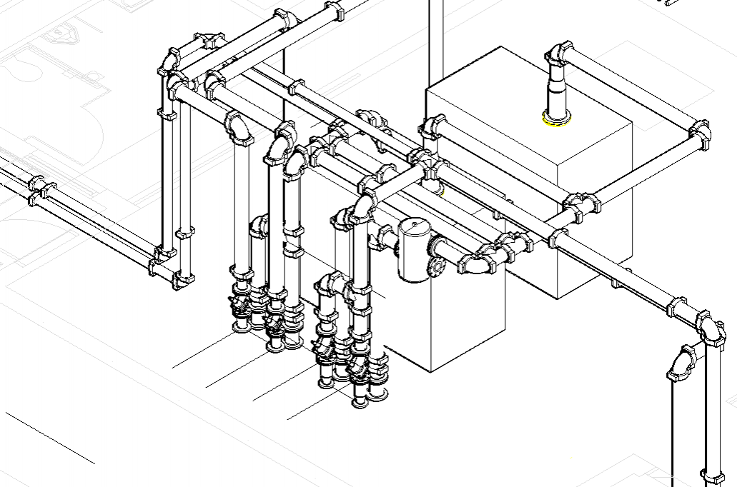
I'm trying to plot in Hidden view but pipes, pumps and other objects are missing when plotting.
I have attached two pictures of how they are shown in paper space and plotting view.
Thanks,
4 REPLIES 4
Message 2 of 5
01-24-2014
01:37 PM
- Mark as New
- Bookmark
- Subscribe
- Mute
- Subscribe to RSS Feed
- Permalink
- Report
01-24-2014
01:37 PM
Are the pumps and pipes AutoCAD MEP objects or Fabrication CADmep objects? Any chance of attaching the drawing so I can test here?
David Pothier
Message 3 of 5
01-27-2014
06:06 AM
- Mark as New
- Bookmark
- Subscribe
- Mute
- Subscribe to RSS Feed
- Permalink
- Report
01-27-2014
06:06 AM
They are MvParts and yes they were created with AutoCAD MEP using Content Builder. I can not attach unfortunately but I've attach a sample drawing with the same issues.
Thanks,
Message 4 of 5
01-27-2014
11:32 AM
- Mark as New
- Bookmark
- Subscribe
- Mute
- Subscribe to RSS Feed
- Permalink
- Report
01-27-2014
11:32 AM
I downloaded your files and experience the same problem with your custom parts. However, if I insert an out of the box part (like a base mounted pump) into the drawing, the out of the box part hides just fine. I'm thinking that there must be a problem with how you created the part. Do any of the custom parts that you have created hide correctly? Can you provide steps on how you built your part?
David Pothier
Message 5 of 5
01-27-2014
12:16 PM
- Mark as New
- Bookmark
- Subscribe
- Mute
- Subscribe to RSS Feed
- Permalink
- Report
01-27-2014
12:16 PM
The funny thing is that now everything is working, now the pumps are shown.
But, still like that drawing that I send you has the same problem now.
I'm confused right now, I just don't get what is going on.
Here are the step of how I built my parts:
Manage > Content Builder > Under "All Installed MvParts (US Imperial)" I have diffrent folders for each custom part that I have.
Select a folder, then click" New Block Part" > Add "Name" and "Description" > "Ok"
Select "Type", "Layer Key", and "Subtype" from the MvPart Builder > "Next"
Click "Add Part Size"(square with plus sign) > Select your part form the list > "None" > "Generate Blocks" > Select "All Directions" > Ok > Next
Select "Generate an Image" > Generate > Next
Right click > Add Pipe Connector > Set all your connections > Ok > Right click on your "Connections" > Edit Placement > Set "Connection Type", "Connection Diameter" and "Nominal Connection" > Select position of your connection/s > Click "Ok"
Click "Next" > Finish
I'm not good at giving steps as you can see![]()
Thanks
Reply
Topic Options
- Subscribe to RSS Feed
- Mark Topic as New
- Mark Topic as Read
- Float this Topic for Current User
- Bookmark
- Subscribe
- Printer Friendly Page

