Community
- Forums Home
- >
- AutoCAD MEP Community
- >
- AutoCAD MEP Forum
- >
- hidden lines in layouts / freezing layers of systems
AutoCAD MEP Forum
Welcome to Autodesk’s AutoCAD MEP Forums. Share your knowledge, ask questions, and explore popular AutoCAD MEP topics.
Turn on suggestions
Auto-suggest helps you quickly narrow down your search results by suggesting possible matches as you type.
hidden lines in layouts / freezing layers of systems
4 REPLIES 4
SOLVED
Reply
Topic Options
- Subscribe to RSS Feed
- Mark Topic as New
- Mark Topic as Read
- Float this Topic for Current User
- Bookmark
- Subscribe
- Printer Friendly Page
Message 1 of 5
03-11-2013
05:17 AM
- Mark as New
- Bookmark
- Subscribe
- Mute
- Subscribe to RSS Feed
- Permalink
- Report
03-11-2013
05:17 AM
Hello,
I have another visual problem with showing the ducts/pipes. I prepared layouts for ploting. 3 layouts: ducts, pipes, ducts+pipes.
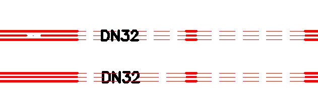
On the layout with ducts+pipes together, crossings of the ducts and pipes are correct, i can see the hidden lines. The problem is, that when i turned off the ducts from the layout with pipes only, the hidden lines of the pipes stayed... I mean the ducts are not visible, but the hidden lines of the pipes which were under the ducts are on. And i would like to see them as "not hidden". In the attached files you can see what i mean.
1 attached file - shows ducts and pipes together
2 attached file - shows pipes after i froze the layer with ducts.
Anyone can help here?
Solved! Go to Solution.
Solved by s.lawrence. Go to Solution.
4 REPLIES 4
Message 2 of 5
03-11-2013
07:03 AM
- Mark as New
- Bookmark
- Subscribe
- Mute
- Subscribe to RSS Feed
- Permalink
- Report
03-11-2013
07:03 AM
After you switch off the layers you want to not be shown, run OBJRELUPDATE and select the whole drawing.
If these models are Xref'd into a finished layout drawing, OBJRELUPDATE will need to be run each time the drawing is opened.
This is a recognised problem and is being investigated (see earlier post in this forum regarding OBJRELUPDATE)
Hope that helps,
Stu
Message 3 of 5
03-12-2013
02:12 AM
- Mark as New
- Bookmark
- Subscribe
- Mute
- Subscribe to RSS Feed
- Permalink
- Report
03-12-2013
02:12 AM
That solved my problem for the moment. It is not perfect (why not automaticly) but as it is reported already than we may expect it will be fixed.
Thank you for your answer 🙂
Regards
Message 4 of 5
05-02-2014
11:54 AM
- Mark as New
- Bookmark
- Subscribe
- Mute
- Subscribe to RSS Feed
- Permalink
- Report
05-02-2014
11:54 AM
Sorry to resurrect this thread, but I'm having this same issue with MEP 2015 and the solution described above does not work for my situation.
Please refer to my attached photo. When I run OBJRELUPDATE in Viewport A, the duct over/under breaks show properly, but Viewport B does not show properly. Running OBJRELUPDATE in Viewport B has the opposite effect - Viewport A will not display the over/under properly.
Running OBJRELUPDATE from model space and paper space does not seem to have an effect.
I have tried using OBJRELUPDATE with HIDEPRECISION set to both 1 and 0.
How can I get both viewports to display correctly without having to put them on separate layouts and run OBJRELUPDATE constantly?
Message 5 of 5
05-06-2014
04:44 AM
- Mark as New
- Bookmark
- Subscribe
- Mute
- Subscribe to RSS Feed
- Permalink
- Report
05-06-2014
04:44 AM
You should be using the Display System to control the look and feel of your ductwork and not your layers in a viewport. You can duplicate your current display representation for Viewport A and give it a unique name. Then go into the system definition of the ductwork that you want to not show up in Viewport B and in the Display Properties tab of the system definition just turn off the ductwork for the Display Representation that you created for Viewport B. It is a difficult process at first but once you get the hang of it you can create the different display representations that you might need pretty quickly.
Reply
Topic Options
- Subscribe to RSS Feed
- Mark Topic as New
- Mark Topic as Read
- Float this Topic for Current User
- Bookmark
- Subscribe
- Printer Friendly Page
