Community
- Forums Home
- >
- Community Archive - Read Only
- >
- AutoCAD Land Desktop (Read Only)
- >
- Strange Surface Lines
AutoCAD Land Desktop (Read Only)
Turn on suggestions
Auto-suggest helps you quickly narrow down your search results by suggesting possible matches as you type.
Reply
Topic Options
- Subscribe to RSS Feed
- Mark Topic as New
- Mark Topic as Read
- Float this Topic for Current User
- Bookmark
- Subscribe
- Printer Friendly Page
Message 1 of 2
03-01-2012
10:27 AM
- Mark as New
- Bookmark
- Subscribe
- Mute
- Subscribe to RSS Feed
- Permalink
- Report
03-01-2012
10:27 AM
Strange Surface Lines
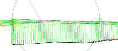
When I am viewing a surface (either volume or terrain) in 3D orbit, the surface is shown with perpendicular lines connecting the boundary of the surface to the datum. In the tutorials, the surfaces do not have these additional lines. My hand calculation of the excavation is about 30% smaller (500 CY) than AutoCAD LD's calculation, so I'm wondering if rather than calculating the difference between my OG surface and my FG surface, AutoCAD is in fact calculating the difference between the FG surface and the datum.
I checked my stratum (correct), surface cross-sections (look accurate), and breaklines (elevation range is correct). I'm all out of ideas, and no one else seems to be having this problem. I've attached a pic of the surface in 3D orbit.
My questions are as follows:
1. Are these merely reference lines to show how the surface connects to my plan drawings, or is it possible AutoCAD is taking a volume surface all the way to my datum?
2. How do I remove these lines / make sure AutoCAD is calculating volumes correctly?
1 REPLY 1
Message 2 of 2
03-01-2012
02:26 PM
- Mark as New
- Bookmark
- Subscribe
- Mute
- Subscribe to RSS Feed
- Permalink
- Report
03-01-2012
02:26 PM
So after some experimentation, it's looking like the problem was that I didn't create non-destructive breaklines at the boundaries. Once I started trimming the boundary edges, my hand calcs matched my cut-fill volumes in AutoCAD.
Reply
Topic Options
- Subscribe to RSS Feed
- Mark Topic as New
- Mark Topic as Read
- Float this Topic for Current User
- Bookmark
- Subscribe
- Printer Friendly Page
