Community
AutoCAD Electrical Forum
Welcome to Autodesk’s AutoCAD Electrical Forums. Share your knowledge, ask questions, and explore popular AutoCAD Electrical topics.
Turn on suggestions
Auto-suggest helps you quickly narrow down your search results by suggesting possible matches as you type.
Reply
Topic Options
- Subscribe to RSS Feed
- Mark Topic as New
- Mark Topic as Read
- Float this Topic for Current User
- Bookmark
- Subscribe
- Printer Friendly Page
- « Previous
-
- 1
- 2
- Next »
Message 1 of 25
Anonymous
1159 Views, 24 Replies
09-11-2011
03:44 AM
- Mark as New
- Bookmark
- Subscribe
- Mute
- Subscribe to RSS Feed
- Permalink
- Report
09-11-2011
03:44 AM
Symbols insertion question!
Hi everybody,
I have started using Autocad Electrical 2010, and I have a question regarding IEC symbols - when I insert 3 pole symbols, for example a 3-pole disconnector or switch, the poles have to little space between them and it doen't look well (check the picture, to see what I mean). I can increase the distance between them manually...but I would like to know if there is a function that does this automaticly?
Any tips and hints are appreciated 🙂
24 REPLIES 24
Message 21 of 25
09-19-2011
02:01 AM
- Mark as New
- Bookmark
- Subscribe
- Mute
- Subscribe to RSS Feed
- Permalink
- Report
09-19-2011
02:01 AM
I understand what you are trying to tell me, but it seems I can not make it work. The cross references are not being labeled as they shoud be. Could you take a look, please? I atached the drawings, just rename the file into rar.
Message 22 of 25
09-19-2011
02:29 AM
- Mark as New
- Bookmark
- Subscribe
- Mute
- Subscribe to RSS Feed
- Permalink
- Report
09-19-2011
02:29 AM
HI..
Attached is your project, setup for cross-referecing according to IEC445/IEC1175.
THL
Trond Hasse Lie
AutoCAD Electrical and EPLAN expert
Ctrl Alt El
Please select "Accept Solution" if this post answers your question. 'Likes' won't hurt either. 😉
Message 23 of 25
06-18-2013
07:55 PM
- Mark as New
- Bookmark
- Subscribe
- Mute
- Subscribe to RSS Feed
- Permalink
- Report
06-18-2013
07:55 PM
Hi Brad, i am having the same problem, can you help me i did set up the formate referenceing to x-y, as well as the setup.
what ather setting do i need to warry about.
ACADE_ZI
Message 24 of 25
06-18-2013
08:58 PM
- Mark as New
- Bookmark
- Subscribe
- Mute
- Subscribe to RSS Feed
- Permalink
- Report
06-18-2013
08:58 PM
You nearly have it all set up.
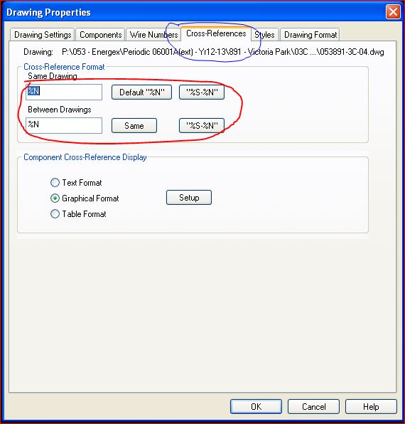
First attachment (CROSS REFERENCE.JPG) shows how I have my cross referencing display set. You can have several parameters displayed beond the Sheet and Number they have as the defaults. You just need to use the correct replacable parameter. See the ACADE help for a list of them.
The second attachment (XY SETUP.JPG) shows how I have my XY referencing set. Yours is similar in this regard apart from the measurements used. Note that you don't need to type in the complete list of co-ordinates if they are in an unbroken sequence.
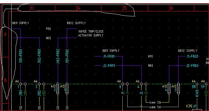
I have cheated slightly here as my title block has attributes along the top that I can change to match what I need. In the case shown, the co-ordinates start at 33 as the two previous dwgs use 1-16 and 17-32. The dwgs have had their co-ordinates changed to match. Along the bottom, I have a set of fields that look to the top co-ordinates and display them, so I only have to change the one set.
The third attachment (AS DISPLAYED.JPG) shows how a parent and child are displayed along with their cross references.
Finally, the first attachment (BORDER.JPG) of the next post shows the top corner of my title block with the X co-ordinates going across the top and the Y co-ordinates going down the side.
Regards Brad
>
Brad Coleman, Electrical Draftsman
Did you find this post helpful? Feel free to Like this post.
Did your question get successfully answered? Then click on the ACCEPT SOLUTION button.
Message 25 of 25
06-18-2013
08:59 PM
- Mark as New
- Bookmark
- Subscribe
- Mute
- Subscribe to RSS Feed
- Permalink
- Report
06-18-2013
08:59 PM
Here's the final attachment as mentioned in my previous post.
Regards Brad
>
Brad Coleman, Electrical Draftsman
Did you find this post helpful? Feel free to Like this post.
Did your question get successfully answered? Then click on the ACCEPT SOLUTION button.
- « Previous
-
- 1
- 2
- Next »
Reply
Topic Options
- Subscribe to RSS Feed
- Mark Topic as New
- Mark Topic as Read
- Float this Topic for Current User
- Bookmark
- Subscribe
- Printer Friendly Page
- « Previous
-
- 1
- 2
- Next »

