Community
AutoCAD Electrical Forum
Welcome to Autodesk’s AutoCAD Electrical Forums. Share your knowledge, ask questions, and explore popular AutoCAD Electrical topics.
Turn on suggestions
Auto-suggest helps you quickly narrow down your search results by suggesting possible matches as you type.
Reply
Topic Options
- Subscribe to RSS Feed
- Mark Topic as New
- Mark Topic as Read
- Float this Topic for Current User
- Bookmark
- Subscribe
- Printer Friendly Page
Message 1 of 13
10-23-2013
06:16 AM
- Mark as New
- Bookmark
- Subscribe
- Mute
- Subscribe to RSS Feed
- Permalink
- Report
10-23-2013
06:16 AM
Location: USA, using ACADE 2013.
I have just been tasked with setting up a few template drawings that our company will use when doing projects that require the IEC symbols. Can someone point me to literature that has tips or guidlines for going metric and using IEC symbols?
Any help is gratefully appreciated.
Scott
Scott G. Sawdy
scott.sawdy@bluecoyotecad.com
scott.sawdy@bluecoyotecad.com
Solved! Go to Solution.
Solved by dougmcalexander. Go to Solution.
12 REPLIES 12
Message 2 of 13
10-23-2013
08:29 PM
- Mark as New
- Bookmark
- Subscribe
- Mute
- Subscribe to RSS Feed
- Permalink
- Report
10-23-2013
08:29 PM
Hello Scott,
In AutoCAD Electrical, there is a default IEC standard project IECDEMO and IEC60617DEMO, you can check the project settings and drawing settings for the default project.
If you don't have the Project in your AutoCAD Electrical, please go to the Control Panel and change AutoCAD Electrical, add the IEC projects from the Add and Remove option.
Thanks,
Robin Shou
Quality Assurance
Autodesk AutoCAD Electrical
Message 3 of 13
10-24-2013
07:29 AM
- Mark as New
- Bookmark
- Subscribe
- Mute
- Subscribe to RSS Feed
- Permalink
- Report
10-24-2013
07:29 AM
Hi Scott,
You will generally want to use an A3 (297x420mm) or A4 (210x297mm) size drawing environment. You could plot to fit an ANSI-B size. You could also use the Modify Symbol Library utility to scale one of the IEC libraries to inches by scaling at 0.03937 scale factor. This would make it possible to design on an 11x17 inch paper size with metric symbols, without the need to scale on insert. The scale on insert doesn't affect dots, angled tees, etc.; called features in the software.
I have seen customers attempt to use the Feature Scale Multiplier (FSM) in drawing properties to try to scale from metric to English or vice versa. It is best to avoid this approach because it can cause undesirable issues with respect to crossreferencing and tagging. I usually tell people who attend my training that the FSM should be used to scale up or down a small bit; a gentle nudge. I recommend not to scale up by more than two, or scale down by less than 0.5. If you find the need to scale beyond those ranges, it is best to scale the entire symbol library with the Modify Symbol Library utility.
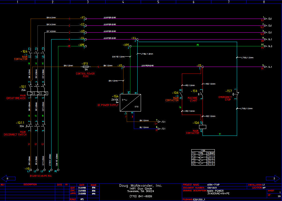
The 3-phase buses and neutral are generally drawn horizontally across the drawings. But the main power usually starts at the lower left of the power distribution page, works its way straight up, through switchgear, and then turns right to go horizontal. Source/destination arrows will pass the potential from page to page. Single-phase power buses (i.e. control voltage) is drawn with the hot bus running horizontally across the top of a page and the common/return running across the bottom.
It is customary to break the schematic up by placing one control device per drawing. For example, a PLC input, an inverter drive, etc.
The IEC library that is included with AutoCAD Electrical tags with a one-letter code, based on IEC61346-2. The IEC60617 library, included with AutoCAD Electrical, tags with the optional two-letter code, based upon the option tables in IEC81346-2. You may wish to check with your customer to determine whether or not they prefer the one-letter or two-letter tags.
There are specific IEC safety directives that should be adhered to. A primary directive for industrial control systems would be IEC60204, the Machinery Directive. You may also reference EN60204, which is the European "harmonized" version of this standard. Basically it is a slightly modified version of IEC60204, as a result of meetings among various members of the European community.
Pay close attention to wire colors. They are different than North America. As of April 1, 2006, they are using Brown, Black, and Gray for L1, L2, L3, respectively, when identifying a wire potential by color. Light Blue is neutral. Red is AC control voltage that is less than mains, phase-to-phase voltage. DC positive is Brown, DC common is Blue, and DC negative is Gray. Foreign or Unknown voltage is orange. Ground is 50% green and 50% yellow (+/- 20% of either). These are just a few to get you started; check the IEC standards for additional details.
I started in the controls industry in Germany, before IEC. But the DIN standards and the British standards became the basis of the IEC standard, which made for an easy transition for me. I have converted numerous North American companies to the IEC standard, so they can ship their systems to Europe and other parts of the world where IEC has become the standard. The on-site workflow-based training course I teach is available for either the JIC/NFPA or IEC standard. We design the same control panel in either course, so the attendees get to see the same control panel designed with each standard. They can compare to the two for future reference. The only difference between the two designs is the U.S. voltage of 480VAC versus the European voltage of 400VAC.
I was right where you are back in 1991, when the company I worked for in Germany was bought by a U.S. company and I was tasked with converting the U.S. team over to the DIN/IEC standards, so their equipment could be accepted globally. I like the IEC standard more than the U.S. standards. Once you get accustomed to it, you realize just how helpful the documentation is for troubleshooting.
Doug McAlexander
Design Engineer/Consultant/Instructor/Mentor specializing in AutoCAD Electrical training and implementation support
Phone and Web-based Support Plans Available
Phone: (770) 841-8009
www.linkedin.com/in/doug-mcalexander-1a77623
Please Accept as Solution if I helped you. Likes are also much appreciated.
Message 4 of 13
11-02-2013
04:10 AM
- Mark as New
- Bookmark
- Subscribe
- Mute
- Subscribe to RSS Feed
- Permalink
- Report
11-02-2013
04:10 AM
It is my 1st time to use AutoCAD electrical, i installed it, and added the liberary of IEC but i can't find it while using the program, i tried to search for the liberary while creating the new project but didnt find anythn as well, how can i find the IEC??
Message 5 of 13
11-02-2013
05:07 AM
- Mark as New
- Bookmark
- Subscribe
- Mute
- Subscribe to RSS Feed
- Permalink
- Report
11-02-2013
05:07 AM
The libraries are in the public path under Users. If you chose to install the IEC library you should also see an IEC demo project in Project Manager. Check the properties of this project and you can see the library path.
Doug McAlexander

Design Engineer/Consultant/Instructor/Mentor specializing in AutoCAD Electrical training and implementation support
Phone and Web-based Support Plans Available
Phone: (770) 841-8009
www.linkedin.com/in/doug-mcalexander-1a77623
Please Accept as Solution if I helped you. Likes are also much appreciated.
Doug McAlexander
Design Engineer/Consultant/Instructor/Mentor specializing in AutoCAD Electrical training and implementation support
Phone and Web-based Support Plans Available
Phone: (770) 841-8009
www.linkedin.com/in/doug-mcalexander-1a77623
Please Accept as Solution if I helped you. Likes are also much appreciated.
Message 6 of 13
11-02-2013
05:11 AM
- Mark as New
- Bookmark
- Subscribe
- Mute
- Subscribe to RSS Feed
- Permalink
- Report
11-02-2013
05:11 AM
the problem is that i can't find the IEC Demo and cant find any files of IEC
Message 7 of 13
11-02-2013
05:16 AM
- Mark as New
- Bookmark
- Subscribe
- Mute
- Subscribe to RSS Feed
- Permalink
- Report
11-02-2013
05:16 AM
If you cannot find any demo projects, you will also be missing the library folder, menu, and sample templates. This would indicate that somehow during the installation process you did not select to install the IEC standard content. Double check by going to Control Panel>Programs and Features and click to uninstall/change AutoCAD Electrical. When the menu appears select to add/remove features.
Doug McAlexander
Design Engineer/Consultant/Instructor/Mentor specializing in AutoCAD Electrical training and implementation support
Phone and Web-based Support Plans Available
Phone: (770) 841-8009
www.linkedin.com/in/doug-mcalexander-1a77623
Please Accept as Solution if I helped you. Likes are also much appreciated.
Message 8 of 13
11-04-2013
08:35 AM
- Mark as New
- Bookmark
- Subscribe
- Mute
- Subscribe to RSS Feed
- Permalink
- Report
Message 9 of 13
11-04-2013
08:38 AM
- Mark as New
- Bookmark
- Subscribe
- Mute
- Subscribe to RSS Feed
- Permalink
- Report
11-04-2013
08:38 AM
I'm glad I was able to help.
Doug McAlexander
Design Engineer/Consultant/Instructor/Mentor specializing in AutoCAD Electrical training and implementation support
Phone and Web-based Support Plans Available
Phone: (770) 841-8009
www.linkedin.com/in/doug-mcalexander-1a77623
Please Accept as Solution if I helped you. Likes are also much appreciated.
Message 10 of 13
03-13-2015
12:26 PM
- Mark as New
- Bookmark
- Subscribe
- Mute
- Subscribe to RSS Feed
- Permalink
- Report
03-13-2015
12:26 PM
Doug,
I attended one of your classes in Atlanta last year. From what i remember, there is a command that will allow me to update all of my schematic symbols from the JIC symbol to an IEC symbol. Am i correct in my interpretation? If so, can you please tell me what the command is?
Message 11 of 13
03-13-2015
12:58 PM
- Mark as New
- Bookmark
- Subscribe
- Mute
- Subscribe to RSS Feed
- Permalink
- Report
03-13-2015
12:58 PM
Make a backup of your project. Go to Swap/Update Block. Down about halfway you will see the option for Library Swap. Navigate to the desired IEC folder you want to swap to. Choose the scale factor of 1/24, or type in 0.03937.
Doug McAlexander
Design Engineer/Consultant/Instructor/Mentor specializing in AutoCAD Electrical training and implementation support
Phone and Web-based Support Plans Available
Phone: (770) 841-8009
www.linkedin.com/in/doug-mcalexander-1a77623
Please Accept as Solution if I helped you. Likes are also much appreciated.
Message 12 of 13
03-13-2015
03:04 PM
- Mark as New
- Bookmark
- Subscribe
- Mute
- Subscribe to RSS Feed
- Permalink
- Report
Message 13 of 13
03-13-2015
03:06 PM
- Mark as New
- Bookmark
- Subscribe
- Mute
- Subscribe to RSS Feed
- Permalink
- Report
03-13-2015
03:06 PM
You are most welcome. Glad to help.
Doug McAlexander
Design Engineer/Consultant/Instructor/Mentor specializing in AutoCAD Electrical training and implementation support
Phone and Web-based Support Plans Available
Phone: (770) 841-8009
www.linkedin.com/in/doug-mcalexander-1a77623
Please Accept as Solution if I helped you. Likes are also much appreciated.
Reply
Topic Options
- Subscribe to RSS Feed
- Mark Topic as New
- Mark Topic as Read
- Float this Topic for Current User
- Bookmark
- Subscribe
- Printer Friendly Page

