Community
AutoCAD Electrical Forum
Welcome to Autodesk’s AutoCAD Electrical Forums. Share your knowledge, ask questions, and explore popular AutoCAD Electrical topics.
Turn on suggestions
Auto-suggest helps you quickly narrow down your search results by suggesting possible matches as you type.
Reply
Topic Options
- Subscribe to RSS Feed
- Mark Topic as New
- Mark Topic as Read
- Float this Topic for Current User
- Bookmark
- Subscribe
- Printer Friendly Page
Message 1 of 29
03-06-2008
04:32 AM
- Mark as New
- Bookmark
- Subscribe
- Mute
- Subscribe to RSS Feed
- Permalink
- Report
03-06-2008
04:32 AM
multi level terminals
Where is the best place to start with multi-level terms? How do I assign wire numbers to each level. I am still not sure what this program is calling "upper" and "Lower" or to "top" and "bottom". Where is the best place to do this?
28 REPLIES 28
Message 2 of 29
03-08-2008
05:53 PM
- Mark as New
- Bookmark
- Subscribe
- Mute
- Subscribe to RSS Feed
- Permalink
- Report
03-08-2008
05:53 PM
Just insert terminal block symbols into the schematic like normal. Assign
the Tag Strip name and terminal number, such as TB1 terminal number 1, TB1
terminal number 2, etc. Do not assign MFG or CAT to the terminals during
schematic creation. Because of the power of the new Terminal Strip Editor,
just wait until you are creating the panel layout to assign part numbers.
You see, sometimes you may decide to use multi-level blocks after you start
the panel layout and realize that you are running short of horizontal DIN
rail space. You may not know this until you start laying out the panel.
Also, if you are an Integrator, you may not know what brand of terminals
your customer wants until later in the design process.
Be sure you assign wire numbers, either automatically per drawing or
project, or manually in case certain wire numbers must follow a predefined
convention.
When you are laying out your panel and it is time to insert the terminal
strip(s) bring up the Terminal Strip Editor. You will notice that the
Terminal Strip tab is the default view and you will see your terminals
listed as single-level blocks. The wires will appear at left and/or right.
Don't worry about their positions just yet. Place your mouse cursor over
the word Terminal and left-click to sort by terminal number. For some
reason they don't appear sorted by terminal number in the default view.
Next go to the Catalog Code Assignment tab and assign the manufacturer and
catalog number. If you have determined that you need to use multi-level
blocks, choose the part number for the particular brand of multi-level
blocks you want. You can drag your mouse cursor across all of the blocks or
use SHIFT or CTRL to select all blocks at once and assign the MFG and CAT
simultaneously to all (another argument for not assigning one at a time
while creating the schematic). Once you have the blocks selected right
click over any block and select Catalog>Assign. Choose the manufacturer and
catalog number of choice.
Why not go ahead and add the End Stops and End Plates as needed by inserting
spares and choosing the appropriate MFG and CAT for them as well? This way
AutoCAD Electrical will load the proper footprint to depict the end plates
and end stops as well. Note: Be sure to unselect all block and select only
the block above or below where you want to insert a spare. Once you assign
the MFG and CAT to a spare it becomes an end stop or end plate, accordingly.
Next, click on the Terminal Strip tab. You will now notice that your blocks
are double-deck, triple-deck or whatever you chose. See my attached
screenshot. This screenshot shows double-deck blocks denoted by L1 for
level 1 and L2 for level 2. The screenshot has red arrows pointing to L1
and L2. The wires are highlighted in the screenshot. In this example all
of these wires will be connected to the right-hand side of the terminal
strip when inserted vertically or the top if the strip is rotated
horizontally before it is inserted.
Now it is time to assign the terminal numbers and wires to the additional
block level, thus cutting the number of blocks needed in half. This is
tricky so be careful. Read these instructions completely before trying it.
We will assume double-deck terminals for this example. 1>Click on terminal
2, the second double-deck terminal in the list. Click on the top line of
the terminal 2 matrix. While terminal 2 is highlighted go to the lower
right of the dialog box and click the Multi-level Associate Terminals
button. Hang with me here. You have selected terminal 2 to associate to
another terminal; in this case we are associating it to terminal 1. In the
Associate Terminals dialog you will see a list of terminals in the strip.
Click on terminal one, the one you wish to associate terminal 2 with. You
will notice that terminal 1 is assigned to the Upper level. You can change
this later if you wish. Next click the Associate button in this same
dialog. You will notice that terminal 2 is assigned to the Lower level.
Note: These level names can be renamed in this dialog if you prefer
something besides Upper and Lower. If you prefer to have terminal 1 on the
Lower and terminal 2 on the Upper, simply click on terminal 2 and then click
the Move Up button or click terminal 2 and click the Move Down button.
Click OK to exit this dialog.
You will now notice that terminal 2 is now associated with terminal block 1
as its lower level. The previous location of terminal 2 is now blank.
Click on it and delete it, unless you want a spare, unmarked block to appear
in the strip. To delete it, select it, right-click, and select
Spare>Delete. Continue the above procedure to associate 4 to 3, 6 to 5,
etc., erasing the left behind spares as you go.
If you want to move wires from left to right or right to left, simply select
the wire and click the Toggle Terminal Destinations button at the bottom of
the Terminal Strip Editor window. You will now see a new box that allows
you to Toggle External to Internal or Internal to External. External and
Internal are relative terms because very often the external wires attach to
the bottom side of a terminal strip that is inserted horizontally. So just
ignore the text and use the arrows as a guide. Toggle External to Internal
effectively toggles from the right-hand side of the block to the left, while
Toggle Internal to External effectively toggles from the left-hand side of
the block to the right.
Once you have your levels associated and your wires positioned, click the
Layout Preview tab. You will now see an example of how your strip will
look, according to the MFG and CAT assignments you made. By default you
will also see wire numbers appearing on the side of the blocks that you
chose to position them. You can use the menu at the left to add wire type
(wire layer), and even the component where the other end of the wire
attaches (tag:terminal). Bear in mind that you are still looking at the
strip as if it will be inserted vertically. If you want to rotate it so it
will be horizontal on the DIN rail, click the list arrow at the bottom
middle of the dialog labeled Angle On Insert and choose 90. Note: The
layout preview will still show a vertical orientation. This is normal. The
Terminal Strip Editor's Layout Preview doesn't currently show any rotated
views of the terminal strip.
I hope this will help you get familiar with the TSE and how it handles
multi-level blocks.
Note: The instructions above are excerpts from the AutoCAD Electrical Basic
Training Tutorial, Copyright 2007-2008 by Doug McAlexander, and should not
be reproduced in any form without written consent from Doug McAlexander.
wrote in message news:5868103@discussion.autodesk.com...
Where is the best place to start with multi-level terms? How do I assign
wire numbers to each level. I am still not sure what this program is calling
"upper" and "Lower" or to "top" and "bottom". Where is the best place to do
this?
Doug McAlexander

Design Engineer/Consultant/Instructor/Mentor specializing in AutoCAD Electrical training and implementation support
Phone and Web-based Support Plans Available
Phone: (770) 841-8009
www.linkedin.com/in/doug-mcalexander-1a77623
Please Accept as Solution if I helped you. Likes are also much appreciated.
the Tag Strip name and terminal number, such as TB1 terminal number 1, TB1
terminal number 2, etc. Do not assign MFG or CAT to the terminals during
schematic creation. Because of the power of the new Terminal Strip Editor,
just wait until you are creating the panel layout to assign part numbers.
You see, sometimes you may decide to use multi-level blocks after you start
the panel layout and realize that you are running short of horizontal DIN
rail space. You may not know this until you start laying out the panel.
Also, if you are an Integrator, you may not know what brand of terminals
your customer wants until later in the design process.
Be sure you assign wire numbers, either automatically per drawing or
project, or manually in case certain wire numbers must follow a predefined
convention.
When you are laying out your panel and it is time to insert the terminal
strip(s) bring up the Terminal Strip Editor. You will notice that the
Terminal Strip tab is the default view and you will see your terminals
listed as single-level blocks. The wires will appear at left and/or right.
Don't worry about their positions just yet. Place your mouse cursor over
the word Terminal and left-click to sort by terminal number. For some
reason they don't appear sorted by terminal number in the default view.
Next go to the Catalog Code Assignment tab and assign the manufacturer and
catalog number. If you have determined that you need to use multi-level
blocks, choose the part number for the particular brand of multi-level
blocks you want. You can drag your mouse cursor across all of the blocks or
use SHIFT or CTRL to select all blocks at once and assign the MFG and CAT
simultaneously to all (another argument for not assigning one at a time
while creating the schematic). Once you have the blocks selected right
click over any block and select Catalog>Assign. Choose the manufacturer and
catalog number of choice.
Why not go ahead and add the End Stops and End Plates as needed by inserting
spares and choosing the appropriate MFG and CAT for them as well? This way
AutoCAD Electrical will load the proper footprint to depict the end plates
and end stops as well. Note: Be sure to unselect all block and select only
the block above or below where you want to insert a spare. Once you assign
the MFG and CAT to a spare it becomes an end stop or end plate, accordingly.
Next, click on the Terminal Strip tab. You will now notice that your blocks
are double-deck, triple-deck or whatever you chose. See my attached
screenshot. This screenshot shows double-deck blocks denoted by L1 for
level 1 and L2 for level 2. The screenshot has red arrows pointing to L1
and L2. The wires are highlighted in the screenshot. In this example all
of these wires will be connected to the right-hand side of the terminal
strip when inserted vertically or the top if the strip is rotated
horizontally before it is inserted.
Now it is time to assign the terminal numbers and wires to the additional
block level, thus cutting the number of blocks needed in half. This is
tricky so be careful. Read these instructions completely before trying it.
We will assume double-deck terminals for this example. 1>Click on terminal
2, the second double-deck terminal in the list. Click on the top line of
the terminal 2 matrix. While terminal 2 is highlighted go to the lower
right of the dialog box and click the Multi-level Associate Terminals
button. Hang with me here. You have selected terminal 2 to associate to
another terminal; in this case we are associating it to terminal 1. In the
Associate Terminals dialog you will see a list of terminals in the strip.
Click on terminal one, the one you wish to associate terminal 2 with. You
will notice that terminal 1 is assigned to the Upper level. You can change
this later if you wish. Next click the Associate button in this same
dialog. You will notice that terminal 2 is assigned to the Lower level.
Note: These level names can be renamed in this dialog if you prefer
something besides Upper and Lower. If you prefer to have terminal 1 on the
Lower and terminal 2 on the Upper, simply click on terminal 2 and then click
the Move Up button or click terminal 2 and click the Move Down button.
Click OK to exit this dialog.
You will now notice that terminal 2 is now associated with terminal block 1
as its lower level. The previous location of terminal 2 is now blank.
Click on it and delete it, unless you want a spare, unmarked block to appear
in the strip. To delete it, select it, right-click, and select
Spare>Delete. Continue the above procedure to associate 4 to 3, 6 to 5,
etc., erasing the left behind spares as you go.
If you want to move wires from left to right or right to left, simply select
the wire and click the Toggle Terminal Destinations button at the bottom of
the Terminal Strip Editor window. You will now see a new box that allows
you to Toggle External to Internal or Internal to External. External and
Internal are relative terms because very often the external wires attach to
the bottom side of a terminal strip that is inserted horizontally. So just
ignore the text and use the arrows as a guide. Toggle External to Internal
effectively toggles from the right-hand side of the block to the left, while
Toggle Internal to External effectively toggles from the left-hand side of
the block to the right.
Once you have your levels associated and your wires positioned, click the
Layout Preview tab. You will now see an example of how your strip will
look, according to the MFG and CAT assignments you made. By default you
will also see wire numbers appearing on the side of the blocks that you
chose to position them. You can use the menu at the left to add wire type
(wire layer), and even the component where the other end of the wire
attaches (tag:terminal). Bear in mind that you are still looking at the
strip as if it will be inserted vertically. If you want to rotate it so it
will be horizontal on the DIN rail, click the list arrow at the bottom
middle of the dialog labeled Angle On Insert and choose 90. Note: The
layout preview will still show a vertical orientation. This is normal. The
Terminal Strip Editor's Layout Preview doesn't currently show any rotated
views of the terminal strip.
I hope this will help you get familiar with the TSE and how it handles
multi-level blocks.
Note: The instructions above are excerpts from the AutoCAD Electrical Basic
Training Tutorial, Copyright 2007-2008 by Doug McAlexander, and should not
be reproduced in any form without written consent from Doug McAlexander.
Where is the best place to start with multi-level terms? How do I assign
wire numbers to each level. I am still not sure what this program is calling
"upper" and "Lower" or to "top" and "bottom". Where is the best place to do
this?
Doug McAlexander
Design Engineer/Consultant/Instructor/Mentor specializing in AutoCAD Electrical training and implementation support
Phone and Web-based Support Plans Available
Phone: (770) 841-8009
www.linkedin.com/in/doug-mcalexander-1a77623
Please Accept as Solution if I helped you. Likes are also much appreciated.
Message 3 of 29
03-08-2008
06:01 PM
- Mark as New
- Bookmark
- Subscribe
- Mute
- Subscribe to RSS Feed
- Permalink
- Report
03-08-2008
06:01 PM
For some reason the entire text did not post earlier. I will try again
below:
Just insert terminal block symbols into the schematic like normal. Assign
the Tag Strip name and terminal number, such as TB1 terminal number 1, TB1
terminal number 2, etc. Do not assign MFG or CAT to the terminals during
schematic creation. Because of the power of the new Terminal Strip Editor,
just wait until you are creating the panel layout to assign part numbers.
You see, sometimes you may decide to use multi-level blocks after you start
the panel layout and realize that you are running short of horizontal DIN
rail space. You may not know this until you start laying out the panel.
Also, if you are an Integrator, you may not know what brand of terminals
your customer wants until later in the design process.
Be sure you assign wire numbers, either automatically per drawing or
project, or manually in case certain wire numbers must follow a predefined
convention.
When you are laying out your panel and it is time to insert the terminal
strip(s) bring up the Terminal Strip Editor. You will notice that the
Terminal Strip tab is the default view and you will see your terminals
listed as single-level blocks. The wires will appear at left and/or right.
Don't worry about their positions just yet. Place your mouse cursor over
the word Terminal and left-click to sort by terminal number. For some
reason they don't appear sorted by terminal number in the default view.
Next go to the Catalog Code Assignment tab and assign the manufacturer and
catalog number. If you have determined that you need to use multi-level
blocks, choose the part number for the particular brand of multi-level
blocks you want. You can drag your mouse cursor across all of the blocks or
use SHIFT or CTRL to select all blocks at once and assign the MFG and CAT
simultaneously to all (another argument for not assigning one at a time
while creating the schematic). Once you have the blocks selected right
click over any block and select Catalog>Assign. Choose the manufacturer and
catalog number of choice.
Why not go ahead and add the End Stops and End Plates as needed by inserting
spares and choosing the appropriate MFG and CAT for them as well? This way
AutoCAD Electrical will load the proper footprint to depict the end plates
and end stops as well. Note: Be sure to unselect all block and select only
the block above or below where you want to insert a spare. Once you assign
the MFG and CAT to a spare it becomes an end stop or end plate, accordingly.
Next, click on the Terminal Strip tab. You will now notice that your blocks
are double-deck, triple-deck or whatever you chose. See my attached
screenshot. This screenshot shows double-deck blocks denoted by L1 for
level 1 and L2 for level 2. The screenshot has red arrows pointing to L1
and L2. The wires are highlighted in the screenshot. In this example all
of these wires will be connected to the right-hand side of the terminal
strip when inserted vertically or the top if the strip is rotated
horizontally before it is inserted.
Now it is time to assign the terminal numbers and wires to the additional
block level, thus cutting the number of blocks needed in half. This is
tricky so be careful. Read these instructions completely before trying it.
We will assume double-deck terminals for this example. 1>Click on terminal
2, the second double-deck terminal in the list. Click on the top line of
the terminal 2 matrix. While terminal 2 is highlighted go to the lower
right of the dialog box and click the Multi-level Associate Terminals
button. Hang with me here. You have selected terminal 2 to associate to
another terminal; in this case we are associating it to terminal 1. In the
Associate Terminals dialog you will see a list of terminals in the strip.
Click on terminal one, the one you wish to associate terminal 2 with. You
will notice that terminal 1 is assigned to the Upper level. You can change
this later if you wish. Next click the Associate button in this same
dialog. You will notice that terminal 2 is assigned to the Lower level.
Note: These level names can be renamed in this dialog if you prefer
something besides Upper and Lower. If you prefer to have terminal 1 on the
Lower and terminal 2 on the Upper, simply click on terminal 2 and then click
the Move Up button or click terminal 2 and click the Move Down button.
Click OK to exit this dialog.
You will now notice that terminal 2 is now associated with terminal block 1
as its lower level. The previous location of terminal 2 is now blank.
Click on it and delete it, unless you want a spare, unmarked block to appear
in the strip. To delete it, select it, right-click, and select
Spare>Delete. Continue the above procedure to associate 4 to 3, 6 to 5,
etc., erasing the left behind spares as you go.
If you want to move wires from left to right or right to left, simply select
the wire and click the Toggle Terminal Destinations button at the bottom of
the Terminal Strip Editor window. You will now see a new box that allows
you to Toggle External to Internal or Internal to External. External and
Internal are relative terms because very often the external wires attach to
the bottom side of a terminal strip that is inserted horizontally. So just
ignore the text and use the arrows as a guide. Toggle External to Internal
effectively toggles from the right-hand side of the block to the left, while
Toggle Internal to External effectively toggles from the left-hand side of
the block to the right.
Once you have your levels associated and your wires positioned, click the
Layout Preview tab. You will now see an example of how your strip will
look, according to the MFG and CAT assignments you made. By default you
will also see wire numbers appearing on the side of the blocks that you
chose to position them. You can use the menu at the left to add wire type
(wire layer), and even the component where the other end of the wire
attaches (tag:terminal). Bear in mind that you are still looking at the
strip as if it will be inserted vertically. If you want to rotate it so it
will be horizontal on the DIN rail, click the list arrow at the bottom
middle of the dialog labeled Angle On Insert and choose 90. Note: The
layout preview will still show a vertical orientation. This is normal. The
Terminal Strip Editor's Layout Preview doesn't currently show any rotated
views of the terminal strip.
I hope this will help you get familiar with the TSE and how it handles
multi-level blocks.
Note: The instructions above are excerpts from the AutoCAD Electrical Basic
Training Tutorial, Copyright 2007-2008 by Doug McAlexander, and should not
be reproduced in any form without written consent from Doug McAlexander.
Doug McAlexander
Design Engineer/Consultant/Instructor/Mentor specializing in AutoCAD Electrical training and implementation support
Phone and Web-based Support Plans Available
Phone: (770) 841-8009
www.linkedin.com/in/doug-mcalexander-1a77623
Please Accept as Solution if I helped you. Likes are also much appreciated.
Message 4 of 29
03-09-2008
05:47 AM
- Mark as New
- Bookmark
- Subscribe
- Mute
- Subscribe to RSS Feed
- Permalink
- Report
03-09-2008
05:47 AM
Thank you.
Why can't Autodesk have a clear explanation in their Help section?
I was able to figure out how to associate terms by the time I read your reply, but the part about doing that later not sooner is great help. Also, deleting after associating and adding end stops is much more clear now.
Thanks again,
Dennis
Message 5 of 29
03-09-2008
06:00 AM
- Mark as New
- Bookmark
- Subscribe
- Mute
- Subscribe to RSS Feed
- Permalink
- Report
03-09-2008
06:00 AM
Thanks again Doug,
Just one quick question, if I know what is in my panel and I know all I will be using is one size/type/brand multi level terminal block, Is there and advantage to not enter the cat. number and terminal strip and number, then use OK-repeat to add all the terms after the schematic is drawn? Then associate them later? Or is it just as easy to associate and add cat # etc later?
Thanks
Message 6 of 29
03-10-2008
06:43 AM
- Mark as New
- Bookmark
- Subscribe
- Mute
- Subscribe to RSS Feed
- Permalink
- Report
03-10-2008
06:43 AM
You can lookup and assign MFG and CAT as you go and repeat insert or copy
catalog. But when you click out of Terminal Strip Editor, AutoCAD
Electrical will update all of the affected terminals with the MFG, CAT,
number of levels, etc. for you automatically.
wrote in message news:5870654@discussion.autodesk.com...
Thanks again Doug,
Just one quick question, if I know what is in my panel and I know all I will
be using is one size/type/brand multi level terminal block, Is there and
advantage to not enter the cat. number and terminal strip and number, then
use OK-repeat to add all the terms after the schematic is drawn? Then
associate them later? Or is it just as easy to associate and add cat # etc
later?
Thanks
Doug McAlexander
Design Engineer/Consultant/Instructor/Mentor specializing in AutoCAD Electrical training and implementation support
Phone and Web-based Support Plans Available
Phone: (770) 841-8009
www.linkedin.com/in/doug-mcalexander-1a77623
Please Accept as Solution if I helped you. Likes are also much appreciated.
catalog. But when you click out of Terminal Strip Editor, AutoCAD
Electrical will update all of the affected terminals with the MFG, CAT,
number of levels, etc. for you automatically.
Thanks again Doug,
Just one quick question, if I know what is in my panel and I know all I will
be using is one size/type/brand multi level terminal block, Is there and
advantage to not enter the cat. number and terminal strip and number, then
use OK-repeat to add all the terms after the schematic is drawn? Then
associate them later? Or is it just as easy to associate and add cat # etc
later?
Thanks
Doug McAlexander
Design Engineer/Consultant/Instructor/Mentor specializing in AutoCAD Electrical training and implementation support
Phone and Web-based Support Plans Available
Phone: (770) 841-8009
www.linkedin.com/in/doug-mcalexander-1a77623
Please Accept as Solution if I helped you. Likes are also much appreciated.
Message 7 of 29
03-10-2008
07:16 AM
- Mark as New
- Bookmark
- Subscribe
- Mute
- Subscribe to RSS Feed
- Permalink
- Report
03-10-2008
07:16 AM
Dennis, some things are hard to explain in words and Autodesk has an
extensive network of training facilities available for us to get
comprehensive instructor-based hands-on training. If you were to attend the
5-day Microsoft Office training course you would be asking why doesn't
Microsoft have a better Help section, because there is so much that you
learn in that class that you don't even know you don't know.
wrote in message news:5870652@discussion.autodesk.com...
Thank you.
Why can't Autodesk have a clear explanation in their Help section?
I was able to figure out how to associate terms by the time I read your
reply, but the part about doing that later not sooner is great help. Also,
deleting after associating and adding end stops is much more clear now.
Thanks again,
Dennis
Doug McAlexander
Design Engineer/Consultant/Instructor/Mentor specializing in AutoCAD Electrical training and implementation support
Phone and Web-based Support Plans Available
Phone: (770) 841-8009
www.linkedin.com/in/doug-mcalexander-1a77623
Please Accept as Solution if I helped you. Likes are also much appreciated.
extensive network of training facilities available for us to get
comprehensive instructor-based hands-on training. If you were to attend the
5-day Microsoft Office training course you would be asking why doesn't
Microsoft have a better Help section, because there is so much that you
learn in that class that you don't even know you don't know.
Thank you.
Why can't Autodesk have a clear explanation in their Help section?
I was able to figure out how to associate terms by the time I read your
reply, but the part about doing that later not sooner is great help. Also,
deleting after associating and adding end stops is much more clear now.
Thanks again,
Dennis
Doug McAlexander
Design Engineer/Consultant/Instructor/Mentor specializing in AutoCAD Electrical training and implementation support
Phone and Web-based Support Plans Available
Phone: (770) 841-8009
www.linkedin.com/in/doug-mcalexander-1a77623
Please Accept as Solution if I helped you. Likes are also much appreciated.
Message 8 of 29
03-10-2008
09:37 AM
- Mark as New
- Bookmark
- Subscribe
- Mute
- Subscribe to RSS Feed
- Permalink
- Report
03-10-2008
09:37 AM
I would love to go to a class. My employer thinks otherwise. I cannot understand that thinking, because I know I could be so much more effective an not to mention faster. We are even a UL Listed Panel building shop so we have to have accurate prints and BOM's. We are trying.
Thanks again for your help.
Dennis
Thanks again for your help.
Dennis
Message 9 of 29
03-10-2008
10:45 AM
- Mark as New
- Bookmark
- Subscribe
- Mute
- Subscribe to RSS Feed
- Permalink
- Report
03-10-2008
10:45 AM
Glad to help Dennis. It's a shame your employer doesn't think training is
important. They have no idea what they are losing in productivity. They
are probably putting pressure on you to deliver the goods without proper
training. That's unfair. I wish you all the best.
wrote in message news:5871402@discussion.autodesk.com...
I would love to go to a class. My employer thinks otherwise. I cannot
understand that thinking, because I know I could be so much more effective
an not to mention faster. We are even a UL Listed Panel building shop so we
have to have accurate prints and BOM's. We are trying.
Thanks again for your help.
Dennis
Doug McAlexander
Design Engineer/Consultant/Instructor/Mentor specializing in AutoCAD Electrical training and implementation support
Phone and Web-based Support Plans Available
Phone: (770) 841-8009
www.linkedin.com/in/doug-mcalexander-1a77623
Please Accept as Solution if I helped you. Likes are also much appreciated.
important. They have no idea what they are losing in productivity. They
are probably putting pressure on you to deliver the goods without proper
training. That's unfair. I wish you all the best.
I would love to go to a class. My employer thinks otherwise. I cannot
understand that thinking, because I know I could be so much more effective
an not to mention faster. We are even a UL Listed Panel building shop so we
have to have accurate prints and BOM's. We are trying.
Thanks again for your help.
Dennis
Doug McAlexander
Design Engineer/Consultant/Instructor/Mentor specializing in AutoCAD Electrical training and implementation support
Phone and Web-based Support Plans Available
Phone: (770) 841-8009
www.linkedin.com/in/doug-mcalexander-1a77623
Please Accept as Solution if I helped you. Likes are also much appreciated.
Message 10 of 29
03-10-2008
12:03 PM
- Mark as New
- Bookmark
- Subscribe
- Mute
- Subscribe to RSS Feed
- Permalink
- Report
03-10-2008
12:03 PM
Doug,
It looks like you know your stuff on how to edit terminal blocks. so here is another question.
First off, I am still learning how to properly draw electrical schematics and coming up with a "standard" at the same time.
What I am trying to do is show one circuit terminal blocks with four wire connection points. This is a one level block, I think; correct me if I’m wrong. Basically we are trying to create a "bus".
But all I can get to work is a separate wire into one terminal block. An example, I have four ground wires to connect to terminal block, on the schematic drawing I have a wire going to its own terminal block symbol. I know want to associate all four blocks into one terminal block with all four wires connecting to it.
Does that make sense?
What I can tell is that a “two” level block creates a two circuit terminal block and I need a four point connection one circuit terminal block.
HELP!
Nathan
Message 11 of 29
03-10-2008
03:28 PM
- Mark as New
- Bookmark
- Subscribe
- Mute
- Subscribe to RSS Feed
- Permalink
- Report
03-10-2008
03:28 PM
Hi Nathan,
Let me see if this will help. Think of the terminal symbols in the
schematic as representing the screws or compression clamps. Each terminal
symbol is one screw or compression clamp. So with my design method I don't
bother with exactly what each screw or compression clamp will be until I get
to the panel layout. It's okay if I know ahead of time, but I just wait
until panel layout to actually assign part numbers. I could assign as I go,
but if I assign BOM data to each terminal symbol in the schematic I may get
4 blocks in my BOM later when I really only need one that has 4 connections.
So I wait until I am in the Terminal Strip Editor to assign part numbers.
It is easier to create the associations to combine 4 screws or compressions
clamps into one block in TSE than doing it at schematic level. At schematic
level the terminals may be spread across many pages. In TSE I see all of
them at once. I can create the associations easily, assign the BOM data and
let the TSE go back and update the schematic symbols with the association
information and BOM data automatically. I did not use the TSE in its
earlier forms but the new version in AcadE 2008 really impressed me. I am
now a big fan of it.
Note: I do not use the internal jumper tool to connect the terminals
together to represent a bus. That is also a newer feature and I devised my
own way back in 1997 when I started using this program. I like to see
something visual on my drawings. So I created a special layer called
JUMPERBAR or just JUMPER. I insert a line between all of the terminal
symbols that will make up a bus and I assign this line to the JUMPER or
JUMPERBAR layer. AcadE automatically knows to ignore a layer with the word
JUMPER in its name from the wire list, so no need to worry about this
appearing on your wire list. So visually I see that there is a physical
connection from screw to screw or compression clamp to compression clamp.
The JUMPERBAR or JUMPER layer is still seen as a current carrying device by
AcadE so wire number/potential is passed through.
If you follow the instructions I posted earlier in this thread and do all of
the associations using Terminal Strip Editor, you can toggle wires from one
side to the other of a terminal and you can effectively move them from one
block to another by creating the association with the other block and
deleting the blank spare that is left behind. Since your blocks have only
one level but 4 connections, you will still need to treat them as having a
Level 1 and Level 2. I would consider the inner two connections as Level 1
and the outer two as Level 2. I modified the footprints of the blocks I use
most with a color code so I can see by the color of the wire numbers exactly
which Level they connection to. See the attached photo from my training
class project where we work with multi-level blocks. This screen shot shows
both triple-deck and double-deck blocks. The numbers represent the screw
lugs in this case and they are the same color as the wire number which
connects to them. This is done by forcing the colors of the attributes to
cyan, green, yellow, etc. in the footprint itself. TSE will automatically
insert the wire numbers according to how you positioned them in the first
screen of TSE, when you created the associations.
wrote in message news:5871598@discussion.autodesk.com...
Doug,
It looks like you know your stuff on how to edit terminal blocks. so here is
another question.
First off, I am still learning how to properly draw electrical schematics
and coming up with a "standard" at the same time.
What I am trying to do is show one circuit terminal blocks with four wire
connection points. This is a one level block, I think; correct me if I'm
wrong. Basically we are trying to create a "bus".
But all I can get to work is a separate wire into one termina
l block. An example, I have four ground wires to connect to terminal block,
on the schematic drawing I have a wire going to its own terminal block
symbol. I know want to associate all four blocks into one terminal block
with all four wires connecting to it.
Does that make sense?
What I can tell is that a "two" level block creates a two circuit terminal
block and I need a four point connection one circuit terminal block.
HELP!
Nathan
Doug McAlexander
Design Engineer/Consultant/Instructor/Mentor specializing in AutoCAD Electrical training and implementation support
Phone and Web-based Support Plans Available
Phone: (770) 841-8009
www.linkedin.com/in/doug-mcalexander-1a77623
Please Accept as Solution if I helped you. Likes are also much appreciated.
Let me see if this will help. Think of the terminal symbols in the
schematic as representing the screws or compression clamps. Each terminal
symbol is one screw or compression clamp. So with my design method I don't
bother with exactly what each screw or compression clamp will be until I get
to the panel layout. It's okay if I know ahead of time, but I just wait
until panel layout to actually assign part numbers. I could assign as I go,
but if I assign BOM data to each terminal symbol in the schematic I may get
4 blocks in my BOM later when I really only need one that has 4 connections.
So I wait until I am in the Terminal Strip Editor to assign part numbers.
It is easier to create the associations to combine 4 screws or compressions
clamps into one block in TSE than doing it at schematic level. At schematic
level the terminals may be spread across many pages. In TSE I see all of
them at once. I can create the associations easily, assign the BOM data and
let the TSE go back and update the schematic symbols with the association
information and BOM data automatically. I did not use the TSE in its
earlier forms but the new version in AcadE 2008 really impressed me. I am
now a big fan of it.
Note: I do not use the internal jumper tool to connect the terminals
together to represent a bus. That is also a newer feature and I devised my
own way back in 1997 when I started using this program. I like to see
something visual on my drawings. So I created a special layer called
JUMPERBAR or just JUMPER. I insert a line between all of the terminal
symbols that will make up a bus and I assign this line to the JUMPER or
JUMPERBAR layer. AcadE automatically knows to ignore a layer with the word
JUMPER in its name from the wire list, so no need to worry about this
appearing on your wire list. So visually I see that there is a physical
connection from screw to screw or compression clamp to compression clamp.
The JUMPERBAR or JUMPER layer is still seen as a current carrying device by
AcadE so wire number/potential is passed through.
If you follow the instructions I posted earlier in this thread and do all of
the associations using Terminal Strip Editor, you can toggle wires from one
side to the other of a terminal and you can effectively move them from one
block to another by creating the association with the other block and
deleting the blank spare that is left behind. Since your blocks have only
one level but 4 connections, you will still need to treat them as having a
Level 1 and Level 2. I would consider the inner two connections as Level 1
and the outer two as Level 2. I modified the footprints of the blocks I use
most with a color code so I can see by the color of the wire numbers exactly
which Level they connection to. See the attached photo from my training
class project where we work with multi-level blocks. This screen shot shows
both triple-deck and double-deck blocks. The numbers represent the screw
lugs in this case and they are the same color as the wire number which
connects to them. This is done by forcing the colors of the attributes to
cyan, green, yellow, etc. in the footprint itself. TSE will automatically
insert the wire numbers according to how you positioned them in the first
screen of TSE, when you created the associations.
Doug,
It looks like you know your stuff on how to edit terminal blocks. so here is
another question.
First off, I am still learning how to properly draw electrical schematics
and coming up with a "standard" at the same time.
What I am trying to do is show one circuit terminal blocks with four wire
connection points. This is a one level block, I think; correct me if I'm
wrong. Basically we are trying to create a "bus".
But all I can get to work is a separate wire into one termina
l block. An example, I have four ground wires to connect to terminal block,
on the schematic drawing I have a wire going to its own terminal block
symbol. I know want to associate all four blocks into one terminal block
with all four wires connecting to it.
Does that make sense?
What I can tell is that a "two" level block creates a two circuit terminal
block and I need a four point connection one circuit terminal block.
HELP!
Nathan
Doug McAlexander
Design Engineer/Consultant/Instructor/Mentor specializing in AutoCAD Electrical training and implementation support
Phone and Web-based Support Plans Available
Phone: (770) 841-8009
www.linkedin.com/in/doug-mcalexander-1a77623
Please Accept as Solution if I helped you. Likes are also much appreciated.
Message 12 of 29
03-10-2008
03:45 PM
- Mark as New
- Bookmark
- Subscribe
- Mute
- Subscribe to RSS Feed
- Permalink
- Report
03-10-2008
03:45 PM
Thanks Doug! I think I'm picking up what your putting down. Ultimately, it sounds like I cant force AutoCAD to use a one level four position block. But I can use a two level block, can I force two different wire "networks" to either side of the terminal block?
The attached picture is an example of what im trying to represent on the schematics. the four ground terminal blocks and ann grounded and "jumpered" via the din rail. The blocks labeled "1" are jumpered using a jumper bar so they are effectively the same network.
Is there any way I could get some of your drawings that show a schematic layout and the terminal block footprint?That way I could see how you getting AutoCAD to combine the blocks into multiple levels with different networks.
Thank you for your help!
Message 13 of 29
03-10-2008
07:32 PM
- Mark as New
- Bookmark
- Subscribe
- Mute
- Subscribe to RSS Feed
- Permalink
- Report
03-10-2008
07:32 PM
What you need to do is assign a different number or letter to each
compression clamp (i.e. 1A, 1B, 1C, 1D or 1, 2, 3, 4) and use the color
coded system to show the wire numbers that attach to each, like in the
example I posted previously. It doesn't matter that your block has 4
connections on one level. The point of the levels in AcadE is that
feed-through blocks elevate each level so they can pass the signal from one
side to the other and both sides would be 1A or 1B, etc. Your block must be
treated as a 4 level block internally jumpered and with no feed-through,
meaning one wire for 1A, one wire for 1B, etc.
The important thing is to denote each terminal symbol in your schematic with
a unique identification like 1A, 1B, etc. When you get to TSE click the
Number column to sort by terminal designator. Then use the Toggle
Destination function to move wires left or right to split them up to show
two wire numbers per side the top two on the right-hand side and the bottom
two on the left-hand side. All you are really doing with this feature is
letting AcadE know on which side of the terminal footprint you want the wire
number info to appear.
Attached is a sample drawing I created with a Wago 4-point front-wiring
ground block. The footprint is the one on the Panel\Wago library folder. I
modified it to include the color-coding system I use to differentiate which
wire connects to which clamp. I will send two more e-mails with
attachments. The first will be the modified block. The second will be a
screenshot with an explanation of how I configured things in the TSE.
wrote in message news:5871884@discussion.autodesk.com...
Thanks Doug! I think I'm picking up what your putting down. Ultimately, it
sounds like I cant force AutoCAD to use a one level four position block. But
I can use a two level block, can I force two different wire "networks" to
either side of the terminal block?
The attached picture is an example of what im trying to represent on the
schematics. the four ground terminal blocks and ann grounded and "jumpered"
via the din rail. The blocks labeled "1" are jumpered using a jumper bar so
they
are effectively the same network.
Is there any way I could get some of your drawings that show a schematic
layout and the terminal block footprint?That way I could see how you getting
AutoCAD to combine the blocks into multiple levels with different networks.
Thank you for your help!
Doug McAlexander
Design Engineer/Consultant/Instructor/Mentor specializing in AutoCAD Electrical training and implementation support
Phone and Web-based Support Plans Available
Phone: (770) 841-8009
www.linkedin.com/in/doug-mcalexander-1a77623
Please Accept as Solution if I helped you. Likes are also much appreciated.
compression clamp (i.e. 1A, 1B, 1C, 1D or 1, 2, 3, 4) and use the color
coded system to show the wire numbers that attach to each, like in the
example I posted previously. It doesn't matter that your block has 4
connections on one level. The point of the levels in AcadE is that
feed-through blocks elevate each level so they can pass the signal from one
side to the other and both sides would be 1A or 1B, etc. Your block must be
treated as a 4 level block internally jumpered and with no feed-through,
meaning one wire for 1A, one wire for 1B, etc.
The important thing is to denote each terminal symbol in your schematic with
a unique identification like 1A, 1B, etc. When you get to TSE click the
Number column to sort by terminal designator. Then use the Toggle
Destination function to move wires left or right to split them up to show
two wire numbers per side the top two on the right-hand side and the bottom
two on the left-hand side. All you are really doing with this feature is
letting AcadE know on which side of the terminal footprint you want the wire
number info to appear.
Attached is a sample drawing I created with a Wago 4-point front-wiring
ground block. The footprint is the one on the Panel\Wago library folder. I
modified it to include the color-coding system I use to differentiate which
wire connects to which clamp. I will send two more e-mails with
attachments. The first will be the modified block. The second will be a
screenshot with an explanation of how I configured things in the TSE.
Thanks Doug! I think I'm picking up what your putting down. Ultimately, it
sounds like I cant force AutoCAD to use a one level four position block. But
I can use a two level block, can I force two different wire "networks" to
either side of the terminal block?
The attached picture is an example of what im trying to represent on the
schematics. the four ground terminal blocks and ann grounded and "jumpered"
via the din rail. The blocks labeled "1" are jumpered using a jumper bar so
they
are effectively the same network.
Is there any way I could get some of your drawings that show a schematic
layout and the terminal block footprint?That way I could see how you getting
AutoCAD to combine the blocks into multiple levels with different networks.
Thank you for your help!
Doug McAlexander
Design Engineer/Consultant/Instructor/Mentor specializing in AutoCAD Electrical training and implementation support
Phone and Web-based Support Plans Available
Phone: (770) 841-8009
www.linkedin.com/in/doug-mcalexander-1a77623
Please Accept as Solution if I helped you. Likes are also much appreciated.
Message 14 of 29
03-10-2008
07:39 PM
- Mark as New
- Bookmark
- Subscribe
- Mute
- Subscribe to RSS Feed
- Permalink
- Report
03-10-2008
07:39 PM
Attached is the modified Wago ground block I used in the example. You can
place this in your C:\Program Files\Autodesk\Acade
2008\Libs\panel\WAGO\TRMS-TERMINAL BLOCKS folder. Save the original block
first as a backup.
wrote in message news:5871993@discussion.autodesk.com...
What you need to do is assign a different number or letter to each
compression clamp (i.e. 1A, 1B, 1C, 1D or 1, 2, 3, 4) and use the color
coded system to show the wire numbers that attach to each, like in the
example I posted previously. It doesn't matter that your block has 4
connections on one level. The point of the levels in AcadE is that
feed-through blocks elevate each level so they can pass the signal from one
side to the other and both sides would be 1A or 1B, etc.
Your block must be
treated as a 4 level block internally jumpered and with no feed-through,
meaning one wire for 1A, one wire for 1B, etc.
The important thing is to denote each terminal symbol in your schematic with
a unique identification like 1A, 1B, etc. When you get to TSE click the
Number column to sort by terminal designator. Then use the Toggle
Destination function to move wires left or right to split them up to show
two wire numbers per side the top two on the
right-hand side and the bottom
two on the left-hand side. All you are really doing with this feature is
letting AcadE know on which side of the terminal footprint you want the wire
number info to appear.
Attached is a sample drawing I created with a Wago 4-point front-wiring
ground block. The footprint is the one on the Panel\Wago library folder. I
modified it to include the color-coding system I use to differentiate which
wire connects to which clamp. I will
send two more e-mails with
attachments. The first will be the modified block. The second will be a
screenshot with an explanation of how I configured things in the TSE.
wrote in message news:5871884@discussion.autodesk.com...
Thanks Doug! I think I'm picking up what your putting down. Ultimately, it
sounds like I cant force AutoCAD to use a one level four position block. But
I can use a two level block, can I force two different wire "networks" to
eith
er side of the terminal block?
The attached picture is an example of what im trying to represent on the
schematics. the four ground terminal blocks and ann grounded and "jumpered"
via the din rail. The blocks labeled "1" are jumpered using a jumper bar so
they
are effectively the same network.
Is there any way I could get some of your drawings that show a schematic
layout and the terminal block footprint?That way I could see how you getting
AutoCAD to combine the blocks int
o multiple levels with different networks.
Thank you for your help!
Doug McAlexander
Design Engineer/Consultant/Instructor/Mentor specializing in AutoCAD Electrical training and implementation support
Phone and Web-based Support Plans Available
Phone: (770) 841-8009
www.linkedin.com/in/doug-mcalexander-1a77623
Please Accept as Solution if I helped you. Likes are also much appreciated.
place this in your C:\Program Files\Autodesk\Acade
2008\Libs\panel\WAGO\TRMS-TERMINAL BLOCKS folder. Save the original block
first as a backup.
What you need to do is assign a different number or letter to each
compression clamp (i.e. 1A, 1B, 1C, 1D or 1, 2, 3, 4) and use the color
coded system to show the wire numbers that attach to each, like in the
example I posted previously. It doesn't matter that your block has 4
connections on one level. The point of the levels in AcadE is that
feed-through blocks elevate each level so they can pass the signal from one
side to the other and both sides would be 1A or 1B, etc.
Your block must be
treated as a 4 level block internally jumpered and with no feed-through,
meaning one wire for 1A, one wire for 1B, etc.
The important thing is to denote each terminal symbol in your schematic with
a unique identification like 1A, 1B, etc. When you get to TSE click the
Number column to sort by terminal designator. Then use the Toggle
Destination function to move wires left or right to split them up to show
two wire numbers per side the top two on the
right-hand side and the bottom
two on the left-hand side. All you are really doing with this feature is
letting AcadE know on which side of the terminal footprint you want the wire
number info to appear.
Attached is a sample drawing I created with a Wago 4-point front-wiring
ground block. The footprint is the one on the Panel\Wago library folder. I
modified it to include the color-coding system I use to differentiate which
wire connects to which clamp. I will
send two more e-mails with
attachments. The first will be the modified block. The second will be a
screenshot with an explanation of how I configured things in the TSE.
Thanks Doug! I think I'm picking up what your putting down. Ultimately, it
sounds like I cant force AutoCAD to use a one level four position block. But
I can use a two level block, can I force two different wire "networks" to
eith
er side of the terminal block?
The attached picture is an example of what im trying to represent on the
schematics. the four ground terminal blocks and ann grounded and "jumpered"
via the din rail. The blocks labeled "1" are jumpered using a jumper bar so
they
are effectively the same network.
Is there any way I could get some of your drawings that show a schematic
layout and the terminal block footprint?That way I could see how you getting
AutoCAD to combine the blocks int
o multiple levels with different networks.
Thank you for your help!
Doug McAlexander
Design Engineer/Consultant/Instructor/Mentor specializing in AutoCAD Electrical training and implementation support
Phone and Web-based Support Plans Available
Phone: (770) 841-8009
www.linkedin.com/in/doug-mcalexander-1a77623
Please Accept as Solution if I helped you. Likes are also much appreciated.
Message 15 of 29
03-10-2008
07:41 PM
- Mark as New
- Bookmark
- Subscribe
- Mute
- Subscribe to RSS Feed
- Permalink
- Report
03-10-2008
07:41 PM
Attached is a screen shot that explains the setup of the 4-point "4-level"
block in TSE.
wrote in message news:5871995@discussion.autodesk.com...
Attached is the modified Wago ground block I used in the example. You can
place this in your C:\Program Files\Autodesk\Acade
2008\Libs\panel\WAGO\TRMS-TERMINAL BLOCKS folder. Save the original block
first as a backup.
wrote in message news:5871993@discussion.autodesk.com...
What you need to do is assign a different number or letter to each
compression clamp (i.e. 1A, 1B, 1C, 1D or 1, 2, 3, 4) and use the color
coded system to show the wire numbers that attach
to each, like in the
example I posted previously. It doesn't matter that your block has 4
connections on one level. The point of the levels in AcadE is that
feed-through blocks elevate each level so they can pass the signal from one
side to the other and both sides would be 1A or 1B, etc.
Your block must be
treated as a 4 level block internally jumpered and with no feed-through,
meaning one wire for 1A, one wire for 1B, etc.
The important thing is to denote each terminal symbol in your schema
tic with
a unique identification like 1A, 1B, etc. When you get to TSE click the
Number column to sort by terminal designator. Then use the Toggle
Destination function to move wires left or right to split them up to show
two wire numbers per side the top two on the
right-hand side and the bottom
two on the left-hand side. All you are really doing with this feature is
letting AcadE know on which side of the terminal footprint you want the wire
number info to appear.
Attached is a sampl
e drawing I created with a Wago 4-point front-wiring
ground block. The footprint is the one on the Panel\Wago library folder. I
modified it to include the color-coding system I use to differentiate which
wire connects to which clamp. I will
send two more e-mails with
attachments. The first will be the modified block. The second will be a
screenshot with an explanation of how I configured things in the TSE.
wrote in message news:5871884@discussion.autodesk.com...
Thanks Do
ug! I think I'm picking up what your putting down. Ultimately, it
sounds like I cant force AutoCAD to use a one level four position block. But
I can use a two level block, can I force two different wire "networks" to
eith
er side of the terminal block?
The attached picture is an example of what im trying to represent on the
schematics. the four ground terminal blocks and ann grounded and "jumpered"
via the din rail. The blocks labeled "1" are jumpered using a jumper bar so
they
are effectively
the same network.
Is there any way I could get some of your drawings that show a schematic
layout and the terminal block footprint?That way I could see how you getting
AutoCAD to combine the blocks int
o multiple levels with different networks.
Thank you for your help!
Doug McAlexander
Design Engineer/Consultant/Instructor/Mentor specializing in AutoCAD Electrical training and implementation support
Phone and Web-based Support Plans Available
Phone: (770) 841-8009
www.linkedin.com/in/doug-mcalexander-1a77623
Please Accept as Solution if I helped you. Likes are also much appreciated.
block in TSE.
Attached is the modified Wago ground block I used in the example. You can
place this in your C:\Program Files\Autodesk\Acade
2008\Libs\panel\WAGO\TRMS-TERMINAL BLOCKS folder. Save the original block
first as a backup.
What you need to do is assign a different number or letter to each
compression clamp (i.e. 1A, 1B, 1C, 1D or 1, 2, 3, 4) and use the color
coded system to show the wire numbers that attach
to each, like in the
example I posted previously. It doesn't matter that your block has 4
connections on one level. The point of the levels in AcadE is that
feed-through blocks elevate each level so they can pass the signal from one
side to the other and both sides would be 1A or 1B, etc.
Your block must be
treated as a 4 level block internally jumpered and with no feed-through,
meaning one wire for 1A, one wire for 1B, etc.
The important thing is to denote each terminal symbol in your schema
tic with
a unique identification like 1A, 1B, etc. When you get to TSE click the
Number column to sort by terminal designator. Then use the Toggle
Destination function to move wires left or right to split them up to show
two wire numbers per side the top two on the
right-hand side and the bottom
two on the left-hand side. All you are really doing with this feature is
letting AcadE know on which side of the terminal footprint you want the wire
number info to appear.
Attached is a sampl
e drawing I created with a Wago 4-point front-wiring
ground block. The footprint is the one on the Panel\Wago library folder. I
modified it to include the color-coding system I use to differentiate which
wire connects to which clamp. I will
send two more e-mails with
attachments. The first will be the modified block. The second will be a
screenshot with an explanation of how I configured things in the TSE.
Thanks Do
ug! I think I'm picking up what your putting down. Ultimately, it
sounds like I cant force AutoCAD to use a one level four position block. But
I can use a two level block, can I force two different wire "networks" to
eith
er side of the terminal block?
The attached picture is an example of what im trying to represent on the
schematics. the four ground terminal blocks and ann grounded and "jumpered"
via the din rail. The blocks labeled "1" are jumpered using a jumper bar so
they
are effectively
the same network.
Is there any way I could get some of your drawings that show a schematic
layout and the terminal block footprint?That way I could see how you getting
AutoCAD to combine the blocks int
o multiple levels with different networks.
Thank you for your help!
Doug McAlexander
Design Engineer/Consultant/Instructor/Mentor specializing in AutoCAD Electrical training and implementation support
Phone and Web-based Support Plans Available
Phone: (770) 841-8009
www.linkedin.com/in/doug-mcalexander-1a77623
Please Accept as Solution if I helped you. Likes are also much appreciated.
Message 16 of 29
03-10-2008
07:46 PM
- Mark as New
- Bookmark
- Subscribe
- Mute
- Subscribe to RSS Feed
- Permalink
- Report
03-10-2008
07:46 PM
Good grief I attached the wring drawing. I'm trying to do too many things
at once. Here is the one I intended.
wrote in message news:5871993@discussion.autodesk.com...
What you need to do is assign a different number or letter to each
compression clamp (i.e. 1A, 1B, 1C, 1D or 1, 2, 3, 4) and use the color
coded system to show the wire numbers that attach to each, like in the
example I posted previously. It doesn't matter that your block has 4
connections on one level. The point of the levels in AcadE is that
feed-through blocks elevate each level so they can pass the signal from one
side to the other and both sides would be 1A or 1B, etc.
Your block must be
treated as a 4 level block internally jumpered and with no feed-through,
meaning one wire for 1A, one wire for 1B, etc.
The important thing is to denote each terminal symbol in your schematic with
a unique identification like 1A, 1B, etc. When you get to TSE click the
Number column to sort by terminal designator. Then use the Toggle
Destination function to move wires left or right to split them up to show
two wire numbers per side the top two on the
right-hand side and the bottom
two on the left-hand side. All you are really doing with this feature is
letting AcadE know on which side of the terminal footprint you want the wire
number info to appear.
Attached is a sample drawing I created with a Wago 4-point front-wiring
ground block. The footprint is the one on the Panel\Wago library folder. I
modified it to include the color-coding system I use to differentiate which
wire connects to which clamp. I will
send two more e-mails with
attachments. The first will be the modified block. The second will be a
screenshot with an explanation of how I configured things in the TSE.
wrote in message news:5871884@discussion.autodesk.com...
Thanks Doug! I think I'm picking up what your putting down. Ultimately, it
sounds like I cant force AutoCAD to use a one level four position block. But
I can use a two level block, can I force two different wire "networks" to
eith
er side of the terminal block?
The attached picture is an example of what im trying to represent on the
schematics. the four ground terminal blocks and ann grounded and "jumpered"
via the din rail. The blocks labeled "1" are jumpered using a jumper bar so
they
are effectively the same network.
Is there any way I could get some of your drawings that show a schematic
layout and the terminal block footprint?That way I could see how you getting
AutoCAD to combine the blocks int
o multiple levels with different networks.
Thank you for your help!
Doug McAlexander
Design Engineer/Consultant/Instructor/Mentor specializing in AutoCAD Electrical training and implementation support
Phone and Web-based Support Plans Available
Phone: (770) 841-8009
www.linkedin.com/in/doug-mcalexander-1a77623
Please Accept as Solution if I helped you. Likes are also much appreciated.
at once. Here is the one I intended.
What you need to do is assign a different number or letter to each
compression clamp (i.e. 1A, 1B, 1C, 1D or 1, 2, 3, 4) and use the color
coded system to show the wire numbers that attach to each, like in the
example I posted previously. It doesn't matter that your block has 4
connections on one level. The point of the levels in AcadE is that
feed-through blocks elevate each level so they can pass the signal from one
side to the other and both sides would be 1A or 1B, etc.
Your block must be
treated as a 4 level block internally jumpered and with no feed-through,
meaning one wire for 1A, one wire for 1B, etc.
The important thing is to denote each terminal symbol in your schematic with
a unique identification like 1A, 1B, etc. When you get to TSE click the
Number column to sort by terminal designator. Then use the Toggle
Destination function to move wires left or right to split them up to show
two wire numbers per side the top two on the
right-hand side and the bottom
two on the left-hand side. All you are really doing with this feature is
letting AcadE know on which side of the terminal footprint you want the wire
number info to appear.
Attached is a sample drawing I created with a Wago 4-point front-wiring
ground block. The footprint is the one on the Panel\Wago library folder. I
modified it to include the color-coding system I use to differentiate which
wire connects to which clamp. I will
send two more e-mails with
attachments. The first will be the modified block. The second will be a
screenshot with an explanation of how I configured things in the TSE.
Thanks Doug! I think I'm picking up what your putting down. Ultimately, it
sounds like I cant force AutoCAD to use a one level four position block. But
I can use a two level block, can I force two different wire "networks" to
eith
er side of the terminal block?
The attached picture is an example of what im trying to represent on the
schematics. the four ground terminal blocks and ann grounded and "jumpered"
via the din rail. The blocks labeled "1" are jumpered using a jumper bar so
they
are effectively the same network.
Is there any way I could get some of your drawings that show a schematic
layout and the terminal block footprint?That way I could see how you getting
AutoCAD to combine the blocks int
o multiple levels with different networks.
Thank you for your help!
Doug McAlexander
Design Engineer/Consultant/Instructor/Mentor specializing in AutoCAD Electrical training and implementation support
Phone and Web-based Support Plans Available
Phone: (770) 841-8009
www.linkedin.com/in/doug-mcalexander-1a77623
Please Accept as Solution if I helped you. Likes are also much appreciated.
Message 17 of 29
03-11-2008
09:03 AM
- Mark as New
- Bookmark
- Subscribe
- Mute
- Subscribe to RSS Feed
- Permalink
- Report
Message 18 of 29
03-12-2008
01:23 PM
- Mark as New
- Bookmark
- Subscribe
- Mute
- Subscribe to RSS Feed
- Permalink
- Report
Message 19 of 29
03-12-2008
08:30 PM
- Mark as New
- Bookmark
- Subscribe
- Mute
- Subscribe to RSS Feed
- Permalink
- Report
03-12-2008
08:30 PM
It isn't quite finished yet. Send me an e-mail direct and I will get you on
the list to be notified. I was to finish it last year but got so busy
traveling and teaching classes onsite that I got behind. But I am working
on the final chapters now.
ECADConsultant@aol.com
wrote in message news:5874079@discussion.autodesk.com...
Doug,
How do I get a copy of the ACADE book you wrote?
Doug McAlexander
Design Engineer/Consultant/Instructor/Mentor specializing in AutoCAD Electrical training and implementation support
Phone and Web-based Support Plans Available
Phone: (770) 841-8009
www.linkedin.com/in/doug-mcalexander-1a77623
Please Accept as Solution if I helped you. Likes are also much appreciated.
the list to be notified. I was to finish it last year but got so busy
traveling and teaching classes onsite that I got behind. But I am working
on the final chapters now.
ECADConsultant@aol.com
Doug,
How do I get a copy of the ACADE book you wrote?
Doug McAlexander
Design Engineer/Consultant/Instructor/Mentor specializing in AutoCAD Electrical training and implementation support
Phone and Web-based Support Plans Available
Phone: (770) 841-8009
www.linkedin.com/in/doug-mcalexander-1a77623
Please Accept as Solution if I helped you. Likes are also much appreciated.
Message 20 of 29
03-19-2008
07:11 AM
- Mark as New
- Bookmark
- Subscribe
- Mute
- Subscribe to RSS Feed
- Permalink
- Report
03-19-2008
07:11 AM
Hi Doug,
Quick question on terminals. When I select and insert a terminal, how do I get it to keep the same wire # on both sides of the term?
Quick question on terminals. When I select and insert a terminal, how do I get it to keep the same wire # on both sides of the term?
Reply
Topic Options
- Subscribe to RSS Feed
- Mark Topic as New
- Mark Topic as Read
- Float this Topic for Current User
- Bookmark
- Subscribe
- Printer Friendly Page


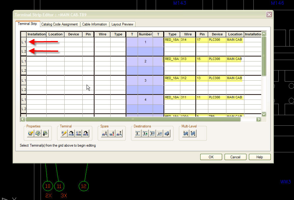
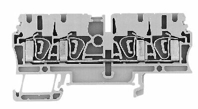