Community
Civil 3D Forum
Welcome to Autodesk’s Civil 3D Forums. Share your knowledge, ask questions, and explore popular AutoCAD Civil 3D topics.
Turn on suggestions
Auto-suggest helps you quickly narrow down your search results by suggesting possible matches as you type.
Reply
Topic Options
- Subscribe to RSS Feed
- Mark Topic as New
- Mark Topic as Read
- Float this Topic for Current User
- Bookmark
- Subscribe
- Printer Friendly Page
- « Previous
- Next »
Message 1 of 44
04-02-2012
12:31 AM
- Mark as New
- Bookmark
- Subscribe
- Mute
- Subscribe to RSS Feed
- Permalink
- Report
04-02-2012
12:31 AM
I am wanting to model a tiered retaining wall with 5' high tiers, 10' apart at 2% grade between tiers. My strategy is to use a corridor with an assembly consisting of a retaining wall subassembly, a conditional cut/fill subassembly and either a daylight or a bench and another tier depending on the cut/fill condition (see attached image).
The problem I am having is the wall subassembly seems to require a target for the height. The help file indicates the height target is optional, so I expect that if I set the target to none in the corridor target settings, the wall height parameter in the subassembly will be used. When I do this the wall does not build. The only way to get it to build is to assign a height target. The only target I have is the existing ground surface and if I use that then the wall projects to EG at the first tier and thus no benching.
Can this approach be made to work without having to create some sort of height target? I'm atttaching the assembly (2012 version) for evaluation.
Neil Wilson (a.k.a. neilw)
AEC Collection/C3D 2024, LDT 2004, Power Civil v8i SS1
WIN 10 64 PRO
http://www.sec-landmgt.com
AEC Collection/C3D 2024, LDT 2004, Power Civil v8i SS1
WIN 10 64 PRO
http://www.sec-landmgt.com
Solved! Go to Solution.
Solved by peterfunkautodesk. Go to Solution.
43 REPLIES 43
Message 41 of 44
04-18-2012
06:14 PM
- Mark as New
- Bookmark
- Subscribe
- Mute
- Subscribe to RSS Feed
- Permalink
- Report
04-18-2012
06:14 PM
Hi Neil,
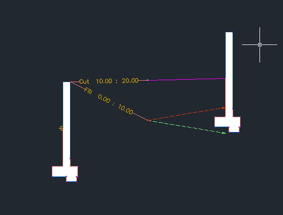
In these two pictures I'm trying to show you the lines to target and the screen where you would do it. You don't need to put any curves on these two corners, just draw a line that would represent the grade break. You set the targets under corridor properties -> Parameters -> "Set all targets" button. That wall subassembly has two targets you can set, one for the surface that it daylights to and the other is an offset target that it can't cross.
Also, to get the corridor to build a surface you go under properties -> Surfaces tab. Then click the "create corridor surface" button. Then you have to add features to the surface you created. In this case add both the "top" links (check add as breakline) and "top" feature lines and it should create the surface. There will be a little bit of cleanup on this one because it draws a few triangles wrong.
Were you able to get this assembly into your drawing and use it to build a corridor?
Thanks,
Mark
Message 42 of 44
04-18-2012
08:15 PM
- Mark as New
- Bookmark
- Subscribe
- Mute
- Subscribe to RSS Feed
- Permalink
- Report
04-18-2012
08:15 PM
Your assembly is working nicely after adding the diagonal miter lines as targets. I'm impressed.
However now I'm having a problem with gaps at the concave corners. I've added small fillets and added sections at the mid points to get the corridor to sample at the miter but it still leaves gaps.
Would you be able to post your design file so I can analyze it?
Neil Wilson (a.k.a. neilw)
AEC Collection/C3D 2024, LDT 2004, Power Civil v8i SS1
WIN 10 64 PRO
http://www.sec-landmgt.com
AEC Collection/C3D 2024, LDT 2004, Power Civil v8i SS1
WIN 10 64 PRO
http://www.sec-landmgt.com
Message 43 of 44
04-24-2012
12:17 PM
- Mark as New
- Bookmark
- Subscribe
- Mute
- Subscribe to RSS Feed
- Permalink
- Report
04-24-2012
12:17 PM
Sorry for the delay in this, I probably should have posted that to begin with.
I was wondering if this paticular scenario is something that Microstation / Bentley can easily resolve. I have never used that software before.
Message 44 of 44
04-24-2012
02:17 PM
- Mark as New
- Bookmark
- Subscribe
- Mute
- Subscribe to RSS Feed
- Permalink
- Report
04-24-2012
02:17 PM
I just took a look at your file Mark. You've done a nice job in getting the wall to form without overlaps and it cleans up pretty well where the tiers transition from cut to fill.
The fillets on the mitered benches still are a problem though. I guess that problem not going to be easily solved using a single assembly from the baseline due to the cross sectional paradigm used by corridors.
I did get my approach to build the individual tiers but I never got it to build a decent surface.
With regard to your question about Bentley's products, I did post the challenge to the Bentley Commnities forum and got 2 results, one using InRoads and one using the new Civil Platform technology that is soon to be released.
The InRoads user said he had to put fillets in the alignment to get it to work but it wasn't difficult to get a result. He posted a 3D PDF but I could see the wall had some problems.
Using the new Civil Platform technology it appears from the screen grab that it handled the task easily.
Here is a link to the post: http://communities.bentley.com/products/road___site_design/f/5922/p/75953/205895.aspx#205895
If you can't access let me know and I'll extract and post it here.
I should mention that I can easily model the benches with Power Civil using the Benched Slope tool but it applies fillets to the tiers.
Neil Wilson (a.k.a. neilw)
AEC Collection/C3D 2024, LDT 2004, Power Civil v8i SS1
WIN 10 64 PRO
http://www.sec-landmgt.com
AEC Collection/C3D 2024, LDT 2004, Power Civil v8i SS1
WIN 10 64 PRO
http://www.sec-landmgt.com
- « Previous
- Next »
Reply
Topic Options
- Subscribe to RSS Feed
- Mark Topic as New
- Mark Topic as Read
- Float this Topic for Current User
- Bookmark
- Subscribe
- Printer Friendly Page
- « Previous
- Next »

