Community
Civil 3D Forum
Welcome to Autodesk’s Civil 3D Forums. Share your knowledge, ask questions, and explore popular AutoCAD Civil 3D topics.
Turn on suggestions
Auto-suggest helps you quickly narrow down your search results by suggesting possible matches as you type.
Reply
Topic Options
- Subscribe to RSS Feed
- Mark Topic as New
- Mark Topic as Read
- Float this Topic for Current User
- Bookmark
- Subscribe
- Printer Friendly Page
Message 1 of 8
04-23-2009
11:57 AM
- Mark as New
- Bookmark
- Subscribe
- Mute
- Subscribe to RSS Feed
- Permalink
- Report
04-23-2009
11:57 AM
Surface from CAD drawing
Hello,
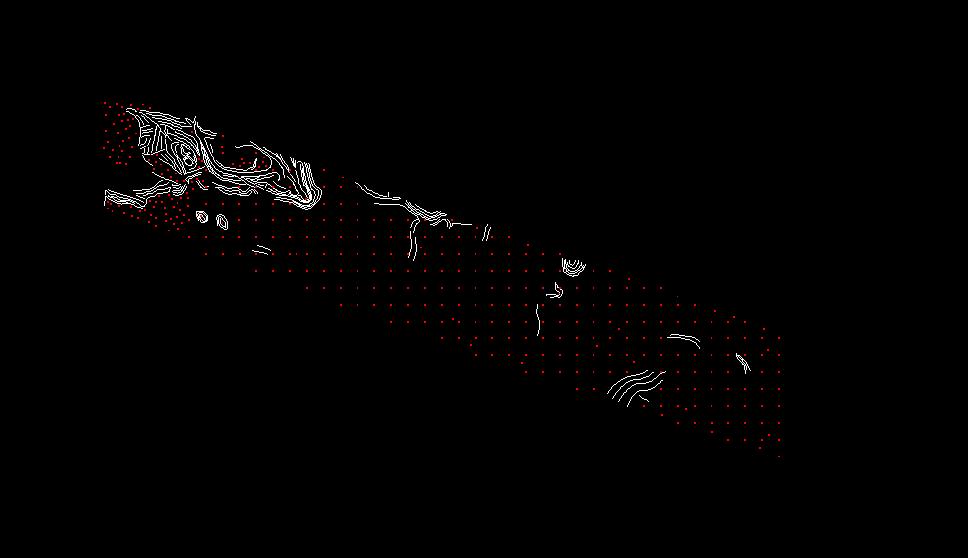
We had an aerial mapper fly the route our new pipeline is to take. I received this file back from and it had far fewer breaklines in it than I expected but contains several of the 'points'. The breaklines are 3d polys and the DTM_points as they called them are AutoCad points with z values. I am new to Civil but have stepped through the tutorials and successfully created a TIN from other drawings with similar breaklines. My question is, based on this data, is my only option to create a TIN surface and should I somehow be using the points as well to build the surface or are they merely reference? I don't expect step by step instructions but I need someone to point me in the right direction. Thanks.
We had an aerial mapper fly the route our new pipeline is to take. I received this file back from and it had far fewer breaklines in it than I expected but contains several of the 'points'. The breaklines are 3d polys and the DTM_points as they called them are AutoCad points with z values. I am new to Civil but have stepped through the tutorials and successfully created a TIN from other drawings with similar breaklines. My question is, based on this data, is my only option to create a TIN surface and should I somehow be using the points as well to build the surface or are they merely reference? I don't expect step by step instructions but I need someone to point me in the right direction. Thanks.
7 REPLIES 7
Message 2 of 8
04-23-2009
12:25 PM
- Mark as New
- Bookmark
- Subscribe
- Mute
- Subscribe to RSS Feed
- Permalink
- Report
04-23-2009
12:25 PM
You should be able to simply create a Surface in C3D, then add the breaklines and autocad points to the surface. Add the acad points as "Drawing Objects".
-- Sinc
http://www.ejsurveying.com
http://www.quuxsoft.com
-- Sinc
http://www.ejsurveying.com
http://www.quuxsoft.com
Sinc
Message 3 of 8
04-23-2009
01:18 PM
- Mark as New
- Bookmark
- Subscribe
- Mute
- Subscribe to RSS Feed
- Permalink
- Report
04-23-2009
01:18 PM
That helps, Thanks. Just knowing that I should be using the points and where to add them in will hopefully allow me to move forward. If you don't mind, I will add to my original question. I can see how the breaklines are used to create the surface but what is the purpose of the points. It seems they are redundant info in many cases. Are they mainly for flatter areas but if that were the case they wouldn't exist throughout the drawing. Thanks again.
Message 4 of 8
04-23-2009
01:31 PM
- Mark as New
- Bookmark
- Subscribe
- Mute
- Subscribe to RSS Feed
- Permalink
- Report
04-23-2009
01:31 PM
Breaklines control how points are connected.
Given a bunch of points for a topo survey, it is possible to connect them in many different ways. The breaklines "guide" the surface creation, so points are not connected in inappropriate ways. Typically, breaklines run along distinct breaks in the grade (thus the name "breaklines"), such as flowlines and tops of curbs, tops and toes of slopes, etc.
The breaklines should be added to your surface as "Breaklines", in addition to adding the Autocad points as "Drawing Objects".
-- Sinc
http://www.ejsurveying.com
http://www.quuxsoft.com
Sinc
Message 5 of 8
04-23-2009
01:39 PM
- Mark as New
- Bookmark
- Subscribe
- Mute
- Subscribe to RSS Feed
- Permalink
- Report
04-23-2009
01:39 PM
The points are the meat of the surface model. The breaklines only control the triangulation and in general do not provide elevation data to the model. By this I mean that during triangulation a breakline will prevent triangles from crossing the breakline. Triangles will always orient themselves such that a side will lie on the breakline and not across the breakline. If there are no "points" at the vertices them elevations are taken from the breakline vertices; else the elevations are taken from the points. You might try an experiment. Create several points, place them at elevation. Connect a few of the points with linework. Place this linework at elevation 0. Now create a surface; add the points; then add the breaklines. But instead of defining them as normal breaks, define them as "Proximity Breaklines". You will see that the surface builds using the points for elevation and breaks for triangulating.
Hope this helps. It was years before I discovered this. And to think I'd been building 3d linework all that time when all I really needed was the cogo I was creating to make drawing the linework easier.
Steve Rogers
Cad manager, DSWA
Hope this helps. It was years before I discovered this. And to think I'd been building 3d linework all that time when all I really needed was the cogo I was creating to make drawing the linework easier.
Steve Rogers
Cad manager, DSWA
Message 6 of 8
04-23-2009
01:50 PM
- Mark as New
- Bookmark
- Subscribe
- Mute
- Subscribe to RSS Feed
- Permalink
- Report
04-23-2009
01:50 PM
Ok, that all makes sense and will help immensely. One last question (maybe). Should I add all the points that are available or should they be added systematically in a design approach similar to the way manual breaks are put in?
Message 7 of 8
04-23-2009
02:26 PM
- Mark as New
- Bookmark
- Subscribe
- Mute
- Subscribe to RSS Feed
- Permalink
- Report
04-23-2009
02:26 PM
Add all the points that lie within the boundary of the model. Piecemeal or one swell foop I don't think makes much difference as long as they all get in the model. And obviously they need to be there when you are "finished" modeling.
Steve Rogers
Cad manager, DSWA
Steve Rogers
Cad manager, DSWA
Reply
Topic Options
- Subscribe to RSS Feed
- Mark Topic as New
- Mark Topic as Read
- Float this Topic for Current User
- Bookmark
- Subscribe
- Printer Friendly Page

