Community
Civil 3D Forum
Welcome to Autodesk’s Civil 3D Forums. Share your knowledge, ask questions, and explore popular AutoCAD Civil 3D topics.
Turn on suggestions
Auto-suggest helps you quickly narrow down your search results by suggesting possible matches as you type.
Reply
Topic Options
- Subscribe to RSS Feed
- Mark Topic as New
- Mark Topic as Read
- Float this Topic for Current User
- Bookmark
- Subscribe
- Printer Friendly Page
Message 1 of 12
08-13-2012
10:28 AM
- Mark as New
- Bookmark
- Subscribe
- Mute
- Subscribe to RSS Feed
- Permalink
- Report
08-13-2012
10:28 AM
stepped slopes in Civil 3D
I am in the process of transitioning from land desktop to Civil 3D. I design roads in steep terrain and sometimes need to have my catch (daylight) slopes change. So my question is, how do I change a daylight slope at a specified depth? For example, from the shoulder of the road I want a 3:1 fill slope to a depth of 10 feet than change to a 2:1 slope until it catches the existing surface. Can this be built into a subassembly such that if the fill is less than 10 feet it will daylight correctly at a 3:1 and if the depth is greater than 10 feet then it carries the 3:1 for 10 vertical feet and then changes to the 2:1 until it daylights?
Thanks,
Jeff
11 REPLIES 11
Message 4 of 12
08-13-2012
12:18 PM
- Mark as New
- Bookmark
- Subscribe
- Mute
- Subscribe to RSS Feed
- Permalink
- Report
08-13-2012
12:18 PM
Also (assuming you're on the Subscription plan), you may want to download the Subassembly Composer from Autodesk Labs. It provides a relatively easy way to create custom Subassemblies that are not in the standard toolbox, and you don't have to do custom programming. If you have access to AU Online, there are some good seminars on there that show you how to use the Subassembly Composer. Once you get the hang of it, it actually works pretty well for a lot of things. Of course, it's best to use a default Subassembly component whenever possible, but this is the next-best option.
Sinc
Message 5 of 12
08-13-2012
01:27 PM
- Mark as New
- Bookmark
- Subscribe
- Mute
- Subscribe to RSS Feed
- Permalink
- Report
08-13-2012
01:27 PM
So I am attempting to do this with the conditional subassembly as John suggested. If I am understanding this correctly (I must not be since its not working quite right yet), the parameters for the type and Minimum and Maximum Distance is what defines which condition to use. Are the distances horizontal or vertical distances?
An additional detail of my project is I am traversing a steep side hill, so my fill slope in some areas can chase the slope quite a ways
Message 6 of 12
08-13-2012
01:44 PM
- Mark as New
- Bookmark
- Subscribe
- Mute
- Subscribe to RSS Feed
- Permalink
- Report
08-13-2012
01:44 PM
The distances are horizontal.
There is a pretty good tutorial for conditional subs in Help that should get you going pretty quick.
http://docs.autodesk.com/CIV3D/2012/ENU/filesCTU/GUID-4CC6F8B3-01A6-4A95-988A-AF9E0A05A87-213.htm
John Mayo
Message 7 of 12
08-13-2012
03:08 PM
- Mark as New
- Bookmark
- Subscribe
- Mute
- Subscribe to RSS Feed
- Permalink
- Report
08-13-2012
03:08 PM
Good question... I haven't needed this recently but come to think of it these types of decisions need to be accounted for regularily. The Subassembly Composer might be your only Autodesk based method to get exactly what you need, however it will take a substantial amount of time to learn it and get a handle on it. The only other option that handles variable conditions well would be section 3d.
Message 8 of 12
08-16-2012
09:11 AM
- Mark as New
- Bookmark
- Subscribe
- Mute
- Subscribe to RSS Feed
- Permalink
- Report
08-16-2012
09:11 AM
So I am still having trouble with this. Just so it is clear as to what I am trying to do I am going to explain it again and then describe what I have tried.
Design scenario: a road traversing up a steep side slope.
Design cross section criteria: cut slope: 1.5:1 slope to daylight
fill slope: 2:1 slope to daylight
if the slope exceeds 20 ft from shoulder, change slope at the 20 ft offset to 0.25:1 (representing a boulder wall at the bottom of the slope)
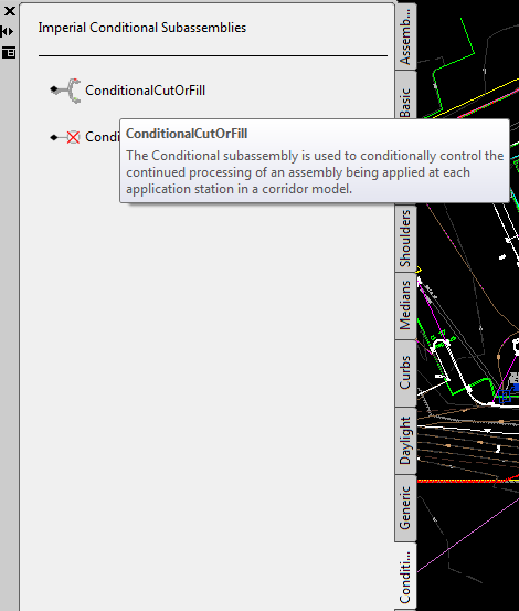
I have tried using the conditional subassemblies. The Conditional Cut of Fill subassembly appears to be conditional based on the input parameters for cut and fill, where the input cut and fill parameters represent the vertical cut or fill at the subassembly connection point. This does not work for this scenario since the shoulder could be in a fill of 2 ft on a side slope of near 2:1 resulting in a design side slope chasing the existing slope much farther than 20 ft (paralleling the existing slope)
I have been trying to work with the conditional horizontal target subassmebly. It appears that I am defining something incorrectly. I attached my assembly for reference. I think my problem is in defining the target. I am trying to define the condtion of use the fill slope to daylight (target) if the target is not found in 20 feet (horizontal) then grade 20ft at 2:1 then daylight at 0.25:1. The current result is that in all fill configurations, it is not finding the target, therefore forcing the 20ft 2:1 slope then daylighting from there (cut or fill).
Any ideas/help?
Thanks
Message 9 of 12
08-16-2012
09:22 AM
- Mark as New
- Bookmark
- Subscribe
- Mute
- Subscribe to RSS Feed
- Permalink
- Report
08-16-2012
09:22 AM
Post your drawing.
Tim Corey
MicroCAD Training and Consulting, Inc.
Redding, CA
Autodesk Gold Reseller
New knowledge is the most valuable commodity on earth. -- Kurt Vonnegut
Message 10 of 12
08-16-2012
10:01 AM
- Mark as New
- Bookmark
- Subscribe
- Mute
- Subscribe to RSS Feed
- Permalink
- Report
08-16-2012
10:01 AM
the drawing file is rather large. Here is a pdf of the corridor in one location that I am having trouble.
Message 11 of 12
05-15-2017
06:42 AM
- Mark as New
- Bookmark
- Subscribe
- Mute
- Subscribe to RSS Feed
- Permalink
- Report
Message 12 of 12
08-21-2021
07:33 PM
- Mark as New
- Bookmark
- Subscribe
- Mute
- Subscribe to RSS Feed
- Permalink
- Report
08-21-2021
07:33 PM
Reply
Topic Options
- Subscribe to RSS Feed
- Mark Topic as New
- Mark Topic as Read
- Float this Topic for Current User
- Bookmark
- Subscribe
- Printer Friendly Page

